Assembly (continued) – Shindaiwa TRIMMER T242X User Manual
Page 9
9
Assembly (continued)
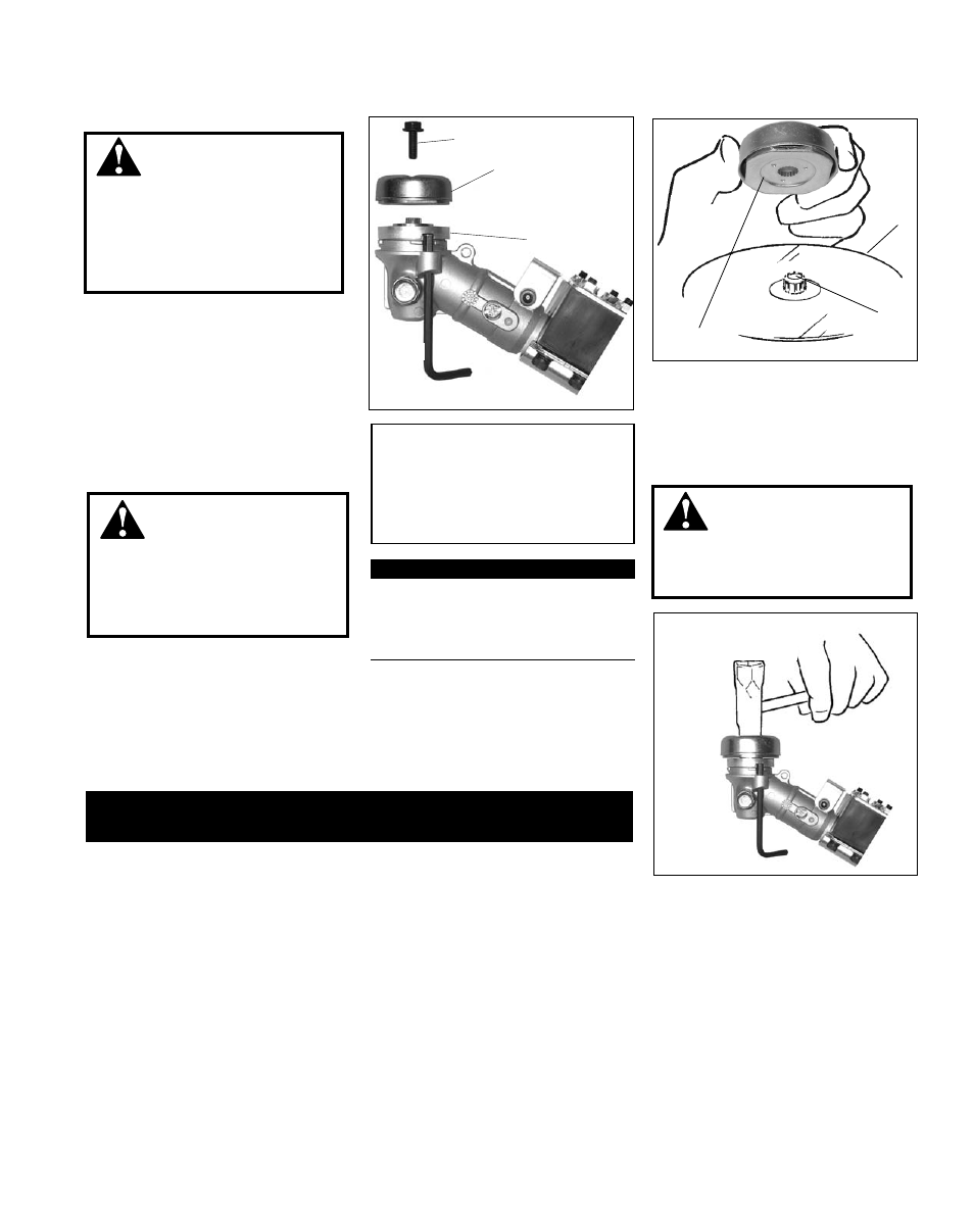
1. Align the notch in blade holder
(A) with the notch in the gear case
flange. Lock the holder and output
shaft by inserting a hex wrench
through the locking hole in the gear
case and into the aligned notches.
2. Remove the shaft bolt (C) and blade
holder (B) from the gear case shaft.
F
B
G
CAUTION!
Install the blade so its printed sur-
face is visible to the operator when
the brushcutter is in the normal
operating position.
WARNING!
The blade must fit flat against the
holder flange. The blade mount-
ing hole must be centered over the
raised boss on blade holder (A).
WARNING!
Holder (B) must fit flush against the
blade and the splines engaged to
the output shaft.
WARNING!
Do not attach any blade to a unit
without proper installation of all
required parts. Failure to use the
proper parts can cause the blade
to fly off and seriously injure the
operator and/or bystanders.
IMPORTANT!
Discard blades that are bent, warped,
cracked, broken or damaged in any way.
Use a sharp blade. A dull blade is more
likely to snag and thrust.
3. Fit the blade (F) over the flange on
holder A.
4. Install blade holder (B) on the output
shaft (G).
Installing Brushcutter Blade
C
B
A
Blade not shown for
clarity
5. Install the shaft bolt (C). Using the combination spark plug wrench/
screwdriver, tighten the bolt firmly in a counter-clockwise direction.
6. Remove the hex wrench.
This unit is now completely assembled and ready to use as a brushcutter.