Assembly – Shindaiwa TRIMMER T242X User Manual
Page 7
7
Prior to Assembly
Before assembling, make sure you
have all the components required for
a complete unit and inspect unit and
components for any damage.
■
Shoulder Harness
■
Barrier Bar
■
Owner’s/operator’s manual
■
Assembly Tool (s)
Assembly
251043
3/16-1/4 inch (4-6 mm)
Throttle Free Play
Adjust Throttle Trigger Free Play
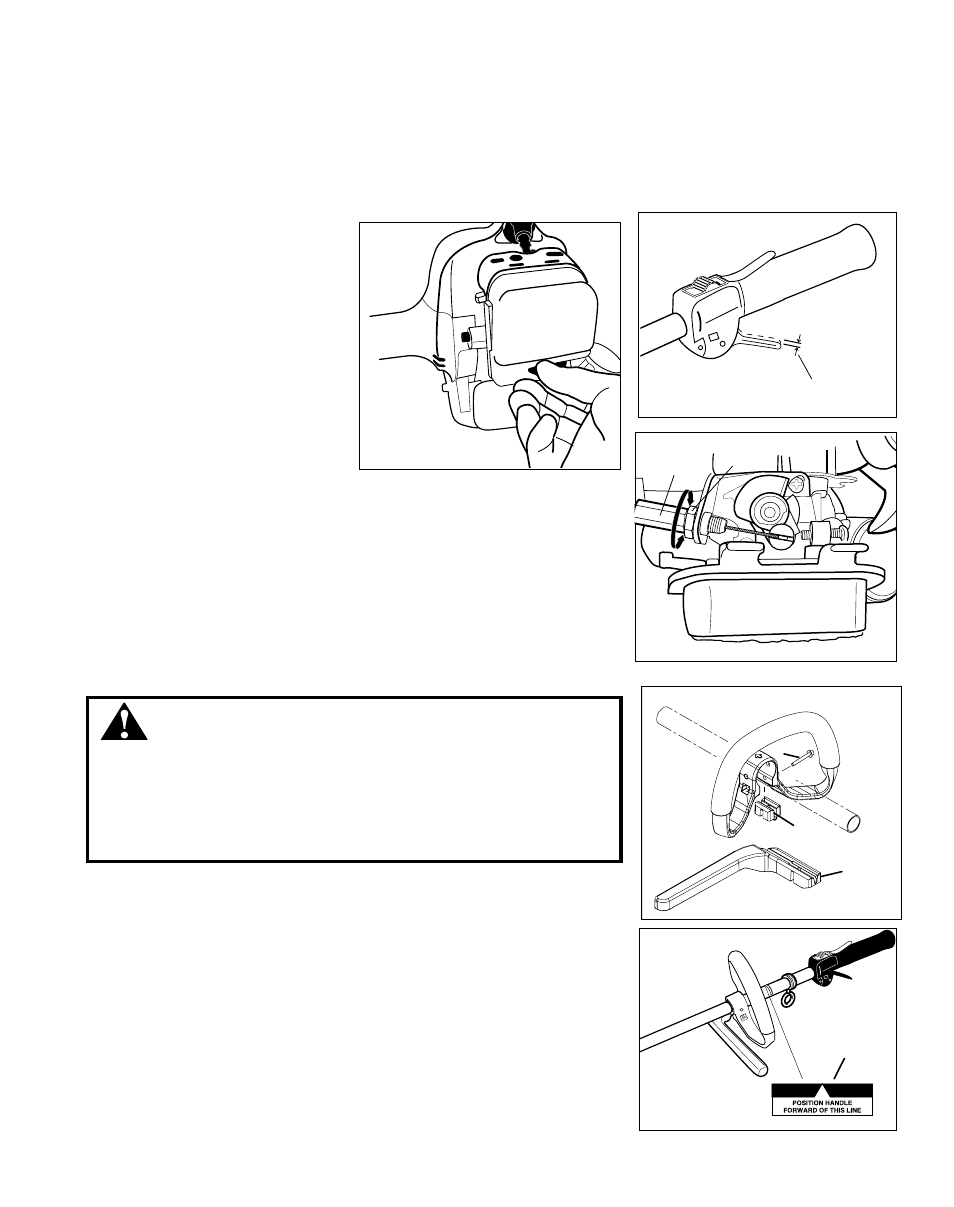
1. Loosen the air cleaner cover knob
and remove the air cleaner cover.
See Figure 7.
2. Loosen the lock nut on the cable
adjuster. See Figure 8.
3. Turn the cable adjuster in or out as
required to obtain proper free play
3/16-1/4 inch (4-6 mm). See Figure
8.
4. Tighten the locknut.
5. Reinstall the air cleaner cover.
Figure 7
Figure 8
The throttle trigger free play should
be approximately 3/16-1/4 inch (4-6
mm). See Figure 6. Make sure that
the throttle trigger operates smoothly
without binding.
If it becomes necessary to adjust the
trigger free play, follow the procedures
and illustrations that follow.
Figure 6
Lock
Nut
Cable
Adjuster
■
Engine and shaft assembly
■
Cutting attachment shield
■
Cutting attachment
■
Nylon spacer
Handle
WARNING!
A standard grass trimmer unit with loop handle should NEVER be operated
with blade-type attachments. For blade use, the trimmer must be fitted with a
bicycle-type handlebar or barrier bar that is located in front of the operator to
reduce the risk of the operator coming in contact with the cutting attachment.
(Per ANSI B175.3). When using a blade, the unit must be equipped with a
harness or strap.
A
B
C
1. Remove bolt (A) and remove handle spacer (B).
2. Position the handle forward of the Handle Positioning Label (D) at the best position for
operator comfort.
3. Install barrier bar (C) and secure with bolt (A).
D