5 10/100 line interface signals, Table 3.6 10/100 line interface signals 24-qfn, 6 analog reference – SMSC FlexPWR LAN8720 User Manual
Page 17: Table 3.7 analog references 24-qfn, 7 power signals, Table 3.8 power signals 24-qfn, 10/100 line interface signals, Analog reference, Power signals, Datasheet
Small Footprint RMII 10/100 Ethernet Transceiver with HP Auto-MDIX Support
Datasheet
SMSC LAN8720/LAN8720i
17
Revision 1.0 (05-28-09)
DATASHEET
3.5
10/100 Line Interface Signals
3.6
Analog Reference
3.7
Power Signals
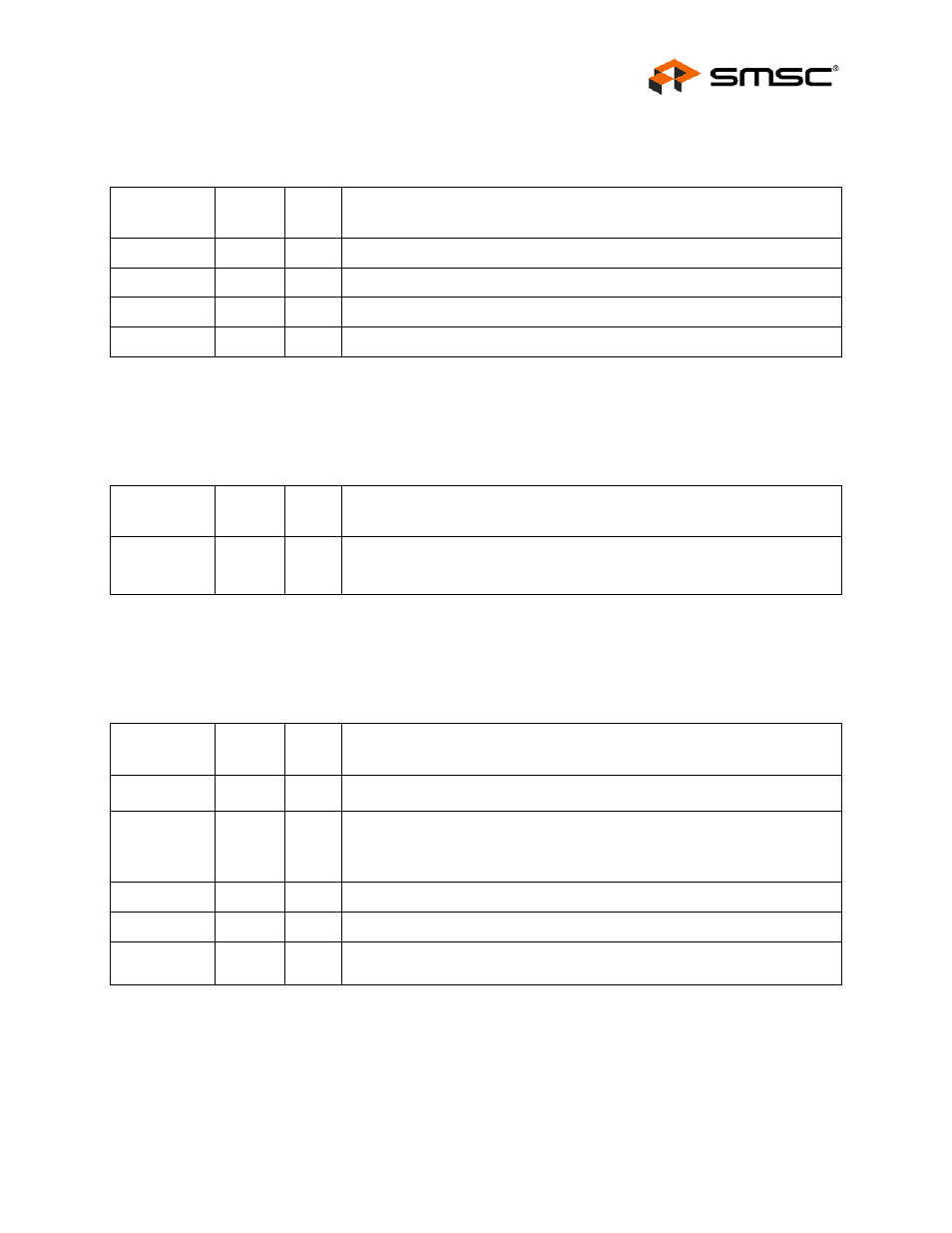
Table 3.6 10/100 Line Interface Signals 24-QFN
SIGNAL
NAME
24-QFN
PIN #
TYPE
DESCRIPTION
TXP
21
AIO
Transmit/Receive Positive Channel 1.
TXN
20
AIO
Transmit/Receive Negative Channel 1.
RXP
23
AIO
Transmit/Receive Positive Channel 2.
RXN
22
AIO
Transmit/Receive Negative Channel 2.
Table 3.7 Analog References 24-QFN
SIGNAL
NAME
24-QFN
PIN #
TYPE
DESCRIPTION
RBIAS
24
AI
External 1% Bias Resistor. Requires an 12.1k resistor to ground connected
as described in the Analog Layout Guidelines. The nominal voltage is 1.2V
and therefore the resistor will dissipate approximately 1mW of power.
Table 3.8 Power Signals 24-QFN
SIGNAL
NAME
24-QFN
PIN #
TYPE
DESCRIPTION
VDDIO
9
P
+1.6V to +3.6V Variable I/O Pad Power
VDDCR
6
P
+1.2V (Core voltage) - 1.2V for digital circuitry on chip. Supplied by the on-
chip regulator unless configured for regulator off mode using the
RXCLK/REGOFF pin. A 1uF decoupling capacitor to ground should be used
on this pin when using the internal 1.2V regulator.
VDD1A
19
P
+3.3V Analog Port Power to Channel 1.
VDD2A
1
P
+3.3V Analog Port Power to Channel 2 and to internal regulator.
VSS
FLAG
GND
The flag must be connected to the ground plane with a via array under the
exposed flag. This is the ground connection for the IC.