Smooth Fitness SMOOTH CE-3.0DS User Manual
Page 6
5
“
A
SSEMBLY
I
NSTRUCTIONS
”
S
TEP
3
–
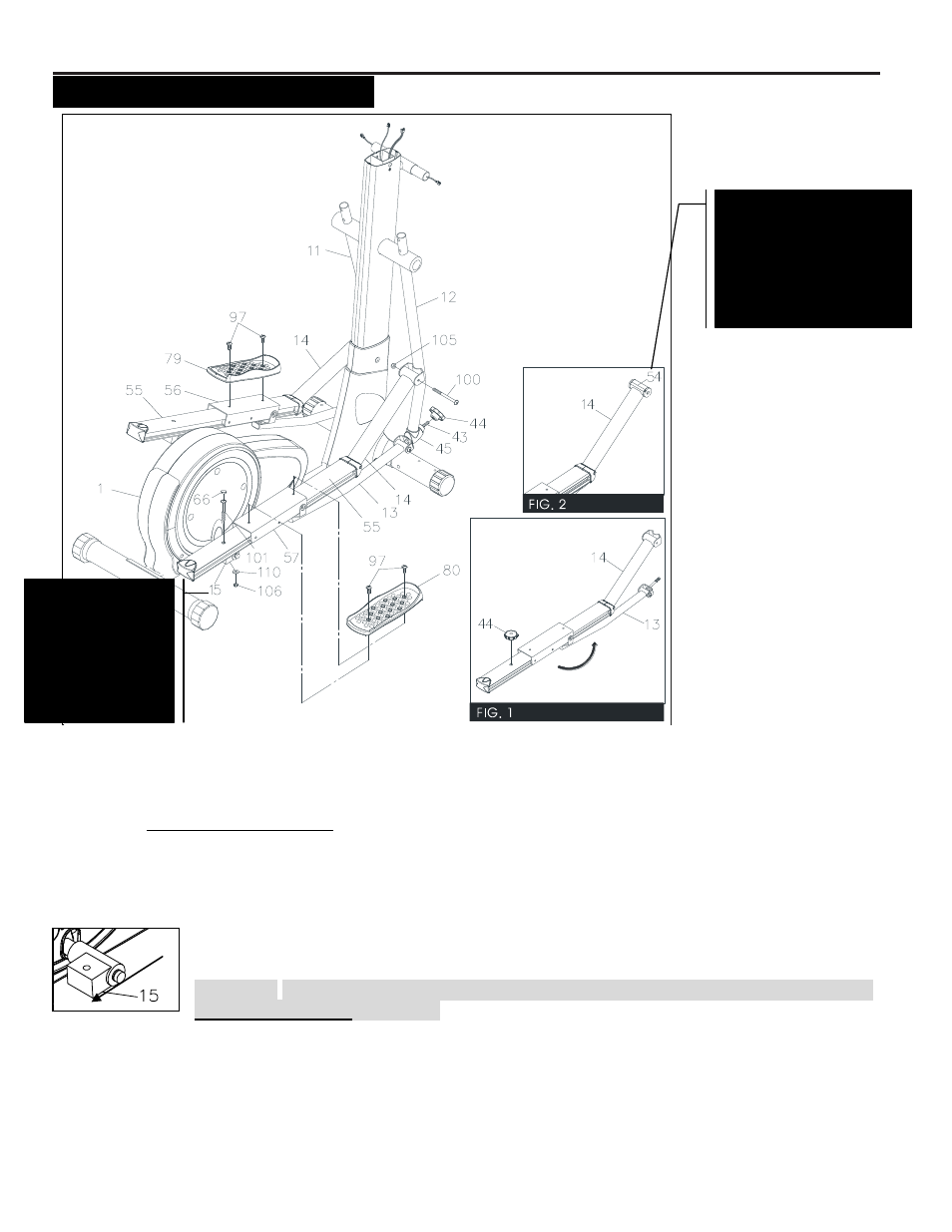
Pedal Arm & Linkage Assembly
a. Connect the PEDAL ARM(14) to the RIGHT Action ARM(12) with 1 x BUTTON HEAD
BOLTS(M8x90mm)(100) and 1 x NYLON LOCK NUTS(M8)(105).
b. Refer to the inset drawing (FIG.1). Remove the LOCKING KNOB(44) from the LINKAGE
CONNECTOR(43). Then swing the LINKAGE(13) toward the front. Insert the LINKAGE CONNECTOR(43)
through the CONNECTOR(45) and secure with the LOCKING KNOB(44).
S
TEP
4
–
Pedal Rail & Pedal Assembly
a. Attach the PEDAL RAIL(55) to the RIGHT PEDAL RAIL CONNECTOR(15) with 1 x
BUTTON HEAD BOLT (M10x85mm)(101), 1 x WASHER(M10)(110), and 1 x NYLON
LOCK NUT(M10)(106).
CAUTION: PEDAL RAIL CONNECTOR (15): The rectangular part should point to the
rear of the machine as shown.
Press the CRANK CAP(66) into the hole on the PEDAL (55)
b. There is a
“L” mark on the LEFT PEDAL (79), and a “R” mark on the RIGHT PEDAL (80). Attach the
RIGHT PEDAL (80) to the RIGHT PEDAL SLIDER(57) with 2 x ROUND HEAD BOLTS(M8x16mm)(97).
c. Repeat the above same procedure on the left side
Prior to assembling
check that Bolt (100)
properly fits through
Shaft Sleeve (54)
located on the Right and
Left Pedal Arm
Assembly (14).
NOTE: Part (15)
must have the
rectangular
portion facing the
rear of the
machine when
installing
the
pedal arm
Back