Configuring the gateway – Schneider Electric Gateway LUFP7 User Manual
Page 61
62
6. Configuring the Gateway
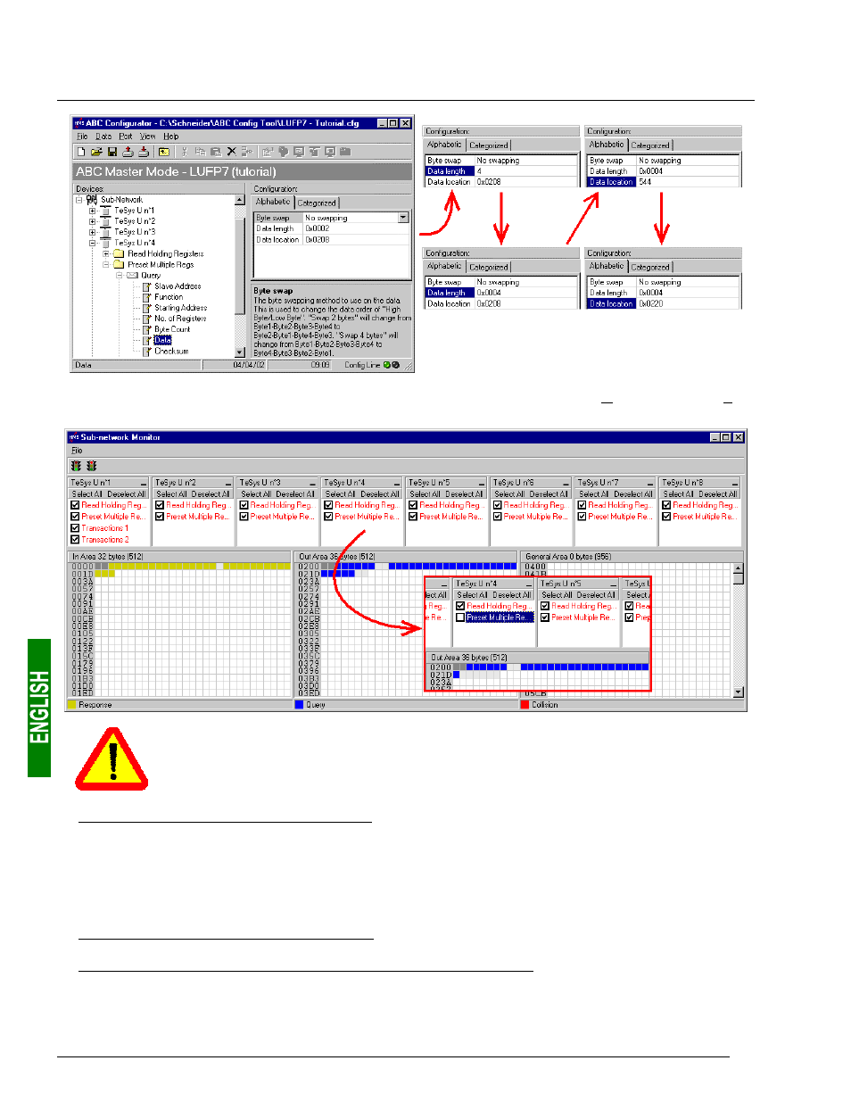
To check that these changes have been entered into the configuration, choose “Monitor” from the “Sub-
Network” menu again:
In point 6), you shall make sure that the total input and ouput sizes of the configured modules
are the same as the exchange sizes displayed in the “Sub-network Monitor.” In the current
example, “In Area 32 bytes” and “Out Area 36 bytes” imply that the modules combined under
SysCon must have a total of 16 IW and 18 OW.
4) Transferring this configuration to the gateway: Please see chapter 6.4 Transferring a Configuration to the
Gateway, page 47. Check that the configuration is valid (LED
s
G
ATEWAY
flashing green). However, the
gateway configuration is now different from the one taken into account by the Profibus-DP coupler with
respect to the gateway (difference in the total length of input data), the LED
q
F
IELDBUS
D
IAG
therefore
becomes flashing red at a frequency of 1 Hz, providing that the gateway is connected to the Profibus-DP
network and to its DPM1 master.
5) Saving this configuration to your PC’s hard disk.
6) Changing the number of data transmitted by the Profibus-DP coupler: Under SyCon, change the list of
modules configured for the gateway (see chapter 4.2.6 Editing and Configuring the Gateway, page 29). Since
we have added 4 bytes after the output data in the gateway memory, the coupler should be configured to
issue an additional 4-byte output data block for the gateway.