Software implementation of the gateway – Schneider Electric Gateway LUFP7 User Manual
Page 33
34
4. Software Implementation of the Gateway
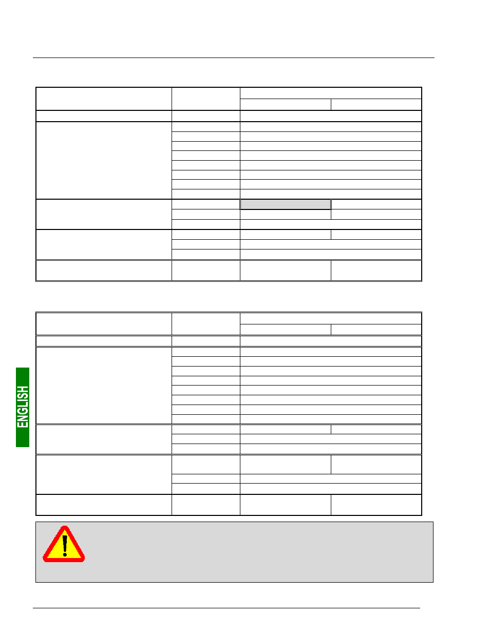
The correspondence between the content of the gateway's input memory (see chapter 10.2.1 Input Data
Memory Area, page 95) and the PLC inputs “%IW4.0” to “%IW4.0.15” is given in the following table:
Description
Service
PLC input
Bit 15....................Bit 8 Bit 7......................Bit 0
Managing the downstream Modbus network
%IW4.0
.00
Gateway status word
%IW4.0.1
0
Value of the motor starter c status register
%IW4.0.2
0
Value of the motor starter d status register
%IW4.0.3
0
Value of the motor starter e status register
%IW4.0.4
0
Value of the motor starter f status register
%IW4.0.5
0
Value of the motor starter g status register
%IW4.0.6
0
Value of the motor starter h status register
%IW4.0.7
0
Value of the motor starter i status register
Periodic communications
—
Monitoring of
TeSys U motor starters
%IW4.0.8
0
Value of the motor starter j status register
%IW4.0.9
0
Free memory location
Slave no. (16#01-16#08)
%IW4.0.10
Function No. (16#03)
Bytes read (16#02)
Aperiodic communications
Reading the value of a motor starter
parameter (R
ESPONSE
)
%IW4.0.11
Value of the parameter read (16#xxxx)
%IW4.0.12
Slave No. (16#01-16#08)
Function No. (16#06)
%IW4.0.13
Address of the parameter written (16#xxxx)
Aperiodic communications
Writing the value of a motor starter
parameter (R
ESPONSE
)
%IW4.0.14
Value of the parameter written (16#xxxx)
Aperiodic communications
(“Trigger bytes” for the responses)
%IW4.0.15
Read parameter
response counter
Write parameter
response counter
The correspondence between the content of the gateway output storage (see chapter 10.2.2 Output Data Memory
Area, page 96) and the outputs of the “%QW4.0” to “%QW4.0.15” automatic controls is as follows:
Description
Service
PLC output
Bit 15....................Bit 8 Bit 7......................Bit 0
Managing the downstream Modbus network
%QW4.0
.00
Profibus-DP master control word
%QW4.0.1
0
Value of the motor starter c command register
%QW4.0.2
0
Value of the motor starter d command register
%QW4.0.3
0
Value of the motor starter e command register
%QW4.0.4
0
Value of the motor starter f command register
%QW4.0.5
0
Value of the motor starter g command register
%QW4.0.6
0
Value of the motor starter h command register
%QW4.0.7
0
Value of the motor starter i command register
Periodic communications
—
Controlling
TeSys U motor starters
%QW4.0.8
0
Value of the motor starter j command register
%QW4.0.9
0
Slave No. (16#01-16#08)
Function No. (16#03)
%QW4.0.10
Address of the parameter to be read (16#xxxx)
Aperiodic communications
Reading the value of a
motor starter parameter (Q
UERY
)
%QW4.0.11
Number of parameters to be read (16#0001)
%QW4.0.12
Slave number
(16#01-16#08)
Function number
(16#06)
%QW4.0.13
Address of the parameter to be written (16#xxxx)
Aperiodic communications
—
Writing the value of a
motor starter parameter (Q
UERY
)
%QW4.0.14
Value of the parameter to be written (16#xxxx)
Aperiodic communications
(“Trigger bytes” for the queries)
%QW4.0.15
Read parameter
query counter
Write parameter
query counter
Whenever you create or change a configuration using AbcConf (see chapter 6 Configuring the
Gateway, page 44), you should be aware that, if you configure an odd number of input (or output)
bytes, PL7 PRO converts the last byte to the 16-bit format instead of leaving it in bits 8-15 of the
last word. Its value is therefore placed into bits 0-7 of the last word.
e.g. If you use 33 input words and the last input word is equal to 16#64 (8-bit format), the word
%IW4.0.16 is therefore equal to 16#0064 (16-bit format) and not 16#64••.