Read holding registers” command \(16#03\), Preset single register” command \(16#06\), Appendix f: modbus commands – Schneider Electric Gateway LUFP7 User Manual
Page 108
109
13. Appendix F: Modbus Commands
Broadcast (1)
Modbus command
0
3
16#03
—
Read Holding Registers
16#06
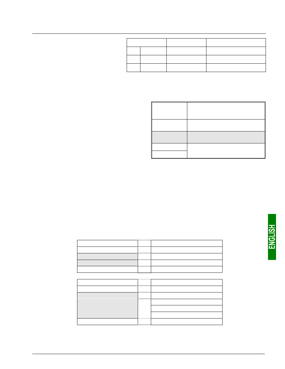
Only the Modbus commands shown in
the right-hand table are supported by
the gateway. The structure of the query
and response frames for each of these
commands is then described in the
following chapters.
16
16#10
Yes
Preset Multiple Registers
(1) The content of this column shows whether the command can be added (“Yes”) or not (“—”) to the list of a
broadcaster node’s commands, known as “Broadcaster” in AbcConf.
Slave Address
- Value cannot be changed (Modbus
address: 1 to 247. Addresses 125,
126, and 127 prohibited)
Function
- Value cannot be changed (code of
the Modbus command)
… Other
fields …
… Specific features of
Modbus commands …
Checksum (Lo)
In the following chapters, each byte of the query and
response frames of a Modbus command are
described, one after another, with the exception of the
fields shown opposite. These are always present in
the queries and responses of all Modbus commands.
The “Slave Address” and “Function” fields are the first
two bytes of these frames. The two bytes of the
“Checksum” are their last two bytes.
Checksum (Hi)
- Type of error check
- Number of the 1st byte checked
The descriptions of the Modbus frames which appear in the following chapters are mainly intended to help you to
configure the gateway’s Modbus exchanges using AbcConf. Please see the documentation of each Modbus
slave to check for any restriction regarding these frames (number of registers which can be read or written in a
single Modbus command, for example).
It is a better idea to get hold of a standard Modbus document, such as the guide entitled Modicon Modbus
Protocol Reference Guide
(ref.: PI-MBUS-300 Rev. J), so that you can see the correspondence between the
elements displayed in AbcConf and the content of the corresponding Modbus frames. Here is an example of a
correspondence for a full frame (including the start and end of frame fields shown above), based on the “Read
Holding Registers” Command (16#03) (see chapter 13.1, page 109):
Elements under AbcConf
Modbus frame fields
Size
Slave Address
Slave no.
1 byte
Function
Function no.
1 byte
Starting Address (Hi, Lo)
No. of the 1st word (MSB / LSB)
2 bytes
Number of points (Hi, Lo)
Number of words (MSB / LSB)
2 bytes
Checksum
CRC16 (LSB / MSB)
2 bytes
Modbus
query
Slave Address
Slave no.
1 byte
Function
Function no.
1 byte
Byte count
Number of bytes read
1 byte
Value of 1st word (MSB / LSB)
2 bytes
…………………………………
Data
Value of last word (MSB / LSB)
2 bytes
Modbus
response
Checksum
CRC16 (LSB / MSB)
2 bytes