SECO-LARM USA Delayed Egress Timer SA-025EQ User Manual
Page 4
ENFORCER Delayed Egress Timer
4
SECO-LARM U.S.A., Inc.
Wiring Diagram:
Installation:
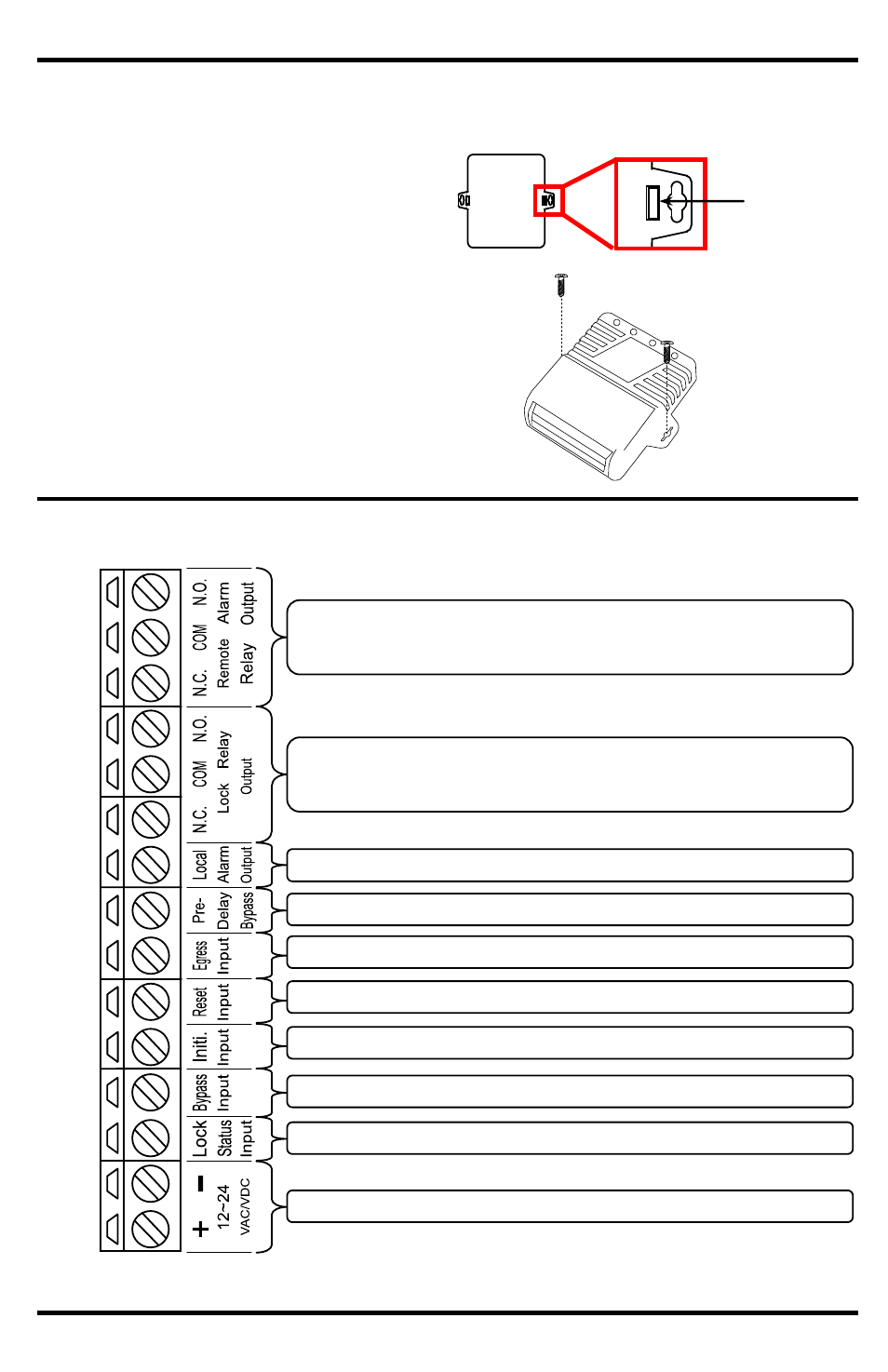
Removing the housing
To remove the housing cover from the
SA-025EQ, use a paper clip or a similar
object to push one of the two tabs on the
back of the unit inward.
Push tab
inward.
Mounting
If mounting is necessary, secure two
screws (not included) through the two
screw holes located on the side of the unit
to a mounting surface.
*Normally energized. (Screen print refers to energized state as normal.)
Remote alarm relay output
(10A@24VDC, Form C Relay, NO/NC/COM)* (see pg. 8)
Lock relay output
(10A@24VDC, Form C Relay, NO/NC/COM)* (see pg. 8)
Local alarm output (500mA@12VDC, transistor ground) (see pg. 8)
Pre-delay bypass input (N.O.+) (see pg. 8)
Free egress input (N.C.+) (see pg. 9)
Reset input (N.C.+) (see pg. 9)
Initiate input (N.C.+) (for unlock device) (see pg. 9)
Bypass input (N.C.+) (see pg. 9)
Lock status input (N.C.+) (see pg. 9)
Power input (12~24 VAC/VDC) (see pg. 9)