English, Hardware installation – SMC Networks SMC7004AWBR User Manual
Page 2
Hardware Installation
2.1
Panel Layout
2.1.1. Front Panel
LEDs monitor the status of each port.
Figure 2-1 Front Panel LED
LED
Function
Colour
Status
Description
POWER
Power indication
Green
On
Power is being applied
to this product.
M1
System status 1
Orange
Blinking
This product is
functioning properly.
M2
System status 2
Orange
On
This product is working
for a specific service.
Blinking
This product is being
configured or upgraded.
Don’t turn it off !
WAN
WAN port activity Green
On
The WAN port is linked.
Blinking
The WAN port is sending
or receiving data.
W.LAN
Wireless activity
Green
Blinking
Sending or receiving data
via wireless
Link/Act. Link status
Green
On
An active station is
1~3
connected to the
corresponding LAN port.
Blinking
The corresponding LAN port
is sending or receiving data.
SPEED
Data Rate
Green
On
Data is transmitting in
1~3
100Mbps on the
corresponding LAN port.
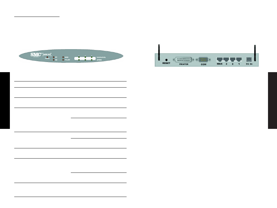
2.1.2. Rear Panel
The rear panel features three 10/100 Mbps Ethernet ports and one
Wide Area network (WAN) port. The WAN port connects your DSL or
cable modem to the router. The LAN ports are used to connect to
your computers or other network devices.
Figure 2-2 Rear Panel Ports
Port
Description
RESET
To reset system settings to factory defaults,
please follow the steps:
1. Power off the device,
2. Press the reset button and hold,
3. Power on the device,
4. Keep the button pressed about 5 seconds,
5. Release the button,
6. Watch the M1 and M2 LEDs, they will flash
8 times and then M1 flashes once per second.
PRINTER
Printer Port (Optional)
COM
Serial port (connect dial-up modem or console cable)
WAN Port
The port where you will connect your cable (or DSL)
modem or Ethernet router.
Port 1-3
The ports where you will connect networked
computers and other devices.
DC IN
Power inlet (DC 12V)
English
English