Schumacher Automatic PS-1562A User Manual
Page 3
3
OPERATING INSTRUCTIONS
12.
Automatic Voltage Detection
When the charger is connected to a battery, it will automatically determine
whether the connected battery is a 6 Volt battery or a 12 Volt battery. This
eliminates the possibility of using the wrong voltage setting.
Automatic Temperature Compensation
The charger adjusts the maximum charge voltage and maximum maintain
voltage based on the ambient air temperature. This permits optimum charging
and safety.
Thermal Runaway
Automatically stops charging to prevent battery from overheating.
Charging
Ensure that all of the charger components are in place and in good
1.
working condition, including the plastic boots on the battery clips.
Connect the battery following the connection instructions described in
2.
Using the Quick-Disconnect Cable Connectors section.
Connect the AC power following the precautions listed in Section 8.
3.
If you’ve connected everything correctly, the CHARGING
4.
(yellow)
LED should be lit indicating that the charger is charging. If the CHARG-
ING
(yellow) LED does not light, check the connections or have
the battery checked/replaced.
Using the Quick-Connect Cable Connectors
Connect either of the two output cable assemblies to the charger in seconds.
Make sure to place the charger on a dry, non-flammable surface like metal or
concrete.
BATTERY CLIPS: Connect the battery clip cable assembly to the charger.
Follow the safety instructions in sections 6 or 7 to connect the output clips to
the battery.
RING TERMINALS: The ring connectors permanently attach the battery provid-
ing easy access to quickly charge your battery. This application is appropri-
ate for motorcycles, lawn tractors, ATV’s and snowmobiles. To permanently
attach it to a battery, loosen and remove each nut from the bolts at the battery
terminals. Connect the red positive ring connector ring to the positive (POS,
P, +) battery terminal. Connect the black negative ring connector ring to the
negative (NEG, N, -) battery terminal. Replace and tighten the nuts to secure it.
Take care to keep both wires and plug away from metal and the engine hood.
Connect the ring connector cable assembly to the charger.
Aborted Charge
If charging can not be completed normally, charging will abort. When charging
aborts, the charger’s output is shut off, and the CHARGING
(yellow) LED
will blink. To reset after an aborted charge, either disconnect the battery or
unplug the charger.
Desulfation Mode
If the battery is left discharged for an extended period of time, it could become
sulfated and not accept a normal charge. If the charger detects a sulfated bat-
tery, the charger will switch to a special mode of operation designed for such
batteries.
Completion of Charge
Charge completion is indicated by the CHARGED
(green) LED. When
lit, the charger has stopped charging and switched to the Maintain Mode of
operation.
Maintain Mode
When the CHARGED
(green) LED is lit, the charger has started Maintain
Mode. In this mode, the charger keeps the battery fully charged by delivering a
small current when necessary. If the battery voltage drops below a preset level,
the charger will go back into Charge Mode until the battery voltage returns to
the full charge level, at which point the charger will return to Maintain Mode.
NOTE: The charger automatically switches between Charge Mode and
Maintain Mode as necessary. The CHARGED
(green) LED may cycle on
when the battery is at full charge and off when the voltage drops below a preset
level and the charger goes into Charge Mode. This cycle will continue, and the
CHARGED
(green) LED will stay on for longer periods of time as the bat-
tery becomes more fully charged.
CALCULATING CHARGE TIME
13.
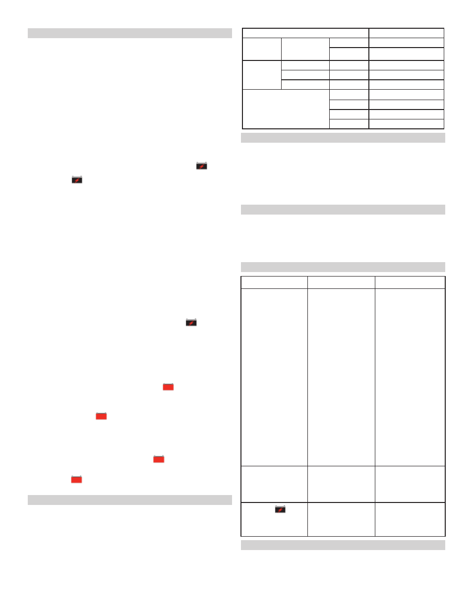
Use the following table to more accurately determine the time it will take to
bring a battery to full charge. First, identify where your battery fits into the chart.
Find your battery’s rating on the chart below, and note the charge time given.
The times given are for batteries with a 50% charge prior to recharging. Add
more time for severely discharged batteries.
BATTERY SIZE/RATING
CHARGING TIME
SMALL
BATTERIES
Motorcycle,
garden
tractor, etc.
6 - 12 AH
2 ½ - 4 hrs
12 - 32 AH
5 - 13 ½ hrs
CARS/
TRUCKS
200 - 315 CCA
40 - 60 RC
15 - 19 ¼ hrs
315 - 550 CCA
60 - 85 RC
19 ¼ - 24 ½ hrs
550 - 1000 CCA
80 - 190 RC
24 ½ - 46 ¼ hrs
MARINE/DEEP CYCLE
80 RC
23 ½ hrs
140 RC
36 ¼ hrs
160 RC
40 hrs
180 RC
44 ¼ hrs
MAINTENANCE INSTRUCTIONS
14.
Before performing maintenance, unplug and disconnect the battery charger
14.1
(see Sections 6, 7 and 8).
After use, unplug the charger and use a dry cloth to wipe all battery corro-
14.2
sion and other dirt or oil from the terminals, cords, and the charger case.
Ensure that all of the charger components are in place and in good working
14.3
condition, including the plastic boots on the battery clips.
Servicing does not require opening the unit, as there are no user-service-
14.4
able parts.
STORAGE INSTRUCTIONS
15.
Store the charger unplugged, in an upright position. The cord will still con-
15.1
duct electricity until it is unplugged from the outlet.
Store inside, in a cool, dry place (unless you’re using an on-board Marine
15.2
Charger).
Do not store the clips on the handle, clipped together, on or around metal, or
15.3
clipped to cables.
TROUBLESHOOTING
16.
PROBLEM
POSSIBLE CAUSE
REASON/SOLUTION
Charger will not turn on
when properly con-
nected.
AC outlet is dead.
Poor electrical connec-
tion.
Severely discharged, but
otherwise good, battery.
Clips are not making a
good connection to the
battery.
Battery is defective.
Reverse connections at
battery.
Check for an open fuse or
circuit breaker supplying
the AC outlet.
Check the power cord
and extension cord for as
loose fitting plug.
The battery may not want
to accept a charge due to
a run-down state. Allow
the charging to continue
until the battery has had
a chance to recover suf-
ficiently enough to take a
charge. If more than 20
minutes, stop charging
and have the battery
checked.
Check for poor connec-
tion to battery and frame.
Make sure connection
points are clean. Rock
clips back and forth for a
better connection.
Have the battery checked.
Unplug the charger and
correct the lead connec-
tions.
Charger makes a loud
buzz or hum.
Transformer laminations
vibrate (buzz).
Shorted Diode Assembly
or Output Rectifier As-
sembly (hum).
No problem, this is a
normal condition.
Have charger checked by
a qualified technician.
CHARGING
(yel-
low) LED is flashing.
Indicates the charger is in
abort mode.
See “Aborted Charge”
in the OPERATING IN-
STRUCTIONS Section.
BEFORE RETURNING FOR REPAIRS
17.
When a charging problem arises, make certain that the battery is capable of
17.1
accepting a normal charge. Use a good battery to double check all connec-
tions, the AC outlet for a full 120-volts, the charger clips for correct polarity
and the quality of the connections from the cables to the clips and from the
clips to the battery system. The clips must be clean.