Seagate ST19171FC User Manual
Page 22
20
Barracuda 9FC Installation Guide, Rev. A
[1]
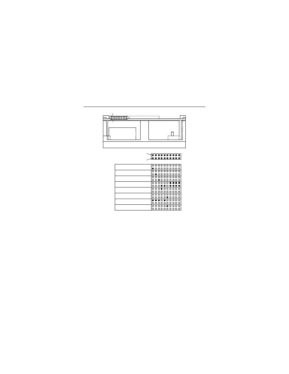
The drive has a 2.2K ohm resistor in series with this LED driver.
Connect the minus side of an external high-efficiency LED (i.e.
2ma) to this pin. Connect the plus side of the LED to +5V.
[2]
An external current limiting resistor is required when connecting an
LED to this pin. The minus side of the resistor/LED combination is
connected to this pin. Connect the plus side to +5V. This pin con-
nects in parallel with the signal of the same name in the J1 interface
connector.
[3]
Jumper storage location is across pins 2 and 4 (horizontally).
Figure 4.
LED indicator connector (J6)
Pin 1
Port A Bypass LED [1]
Pin 1
Pin 2
J6
Port B Bypass LED [1]
Fault LED [2]
Reserved
Active LED [2]
+5V
Ground [3]
Active LED [1]
Pin 2
J6
See also other documents in the category Seagate Hardware:
- Barracuda ST3200826A (48 pages)
- BARRACUDA ST3120023AS (2 pages)
- BARRACUDA ST3750840AS (68 pages)
- 1270SL (40 pages)
- BARRACUDA ST1181677LW (2 pages)
- Barracuda ST3750640NS (2 pages)
- BARRACUDA ST3500641AS (2 pages)
- BARRACUDA XT SERIES SATA ST32000641AS (42 pages)
- SV35.3 Series Serial ATA ST31000340SV (54 pages)
- BARRACUDA ST31500341AS (50 pages)
- BARRACUDA ST3750525AS (48 pages)
- Cheetah 15K.5 SAS ST3300655SS (86 pages)
- BARRACUDA 7200.11 SERIAL ATA ST3500620AS (48 pages)
- U4 ST32112A (42 pages)
- BARRACUDA ST3400632AS (50 pages)
- BARRACUDA ST3160316AS (48 pages)
- BARRACUDA ST31000640SS (82 pages)
- U8TM FAMILY ST317221A (2 pages)
- U10TM ST315323A (2 pages)
- BlackArmor WS 110 (2 pages)
- Barracuda ST3160023A (52 pages)
- CONSTELLATION ES SERIAL ATA ST32000644NS (48 pages)
- BARRACUDA ST360021A (2 pages)
- U Series 9 ST380012A (2 pages)
- BARRACUDA ST3320613AS (48 pages)
- DB35 Serial ATA ST3400832SCE (44 pages)
- Barracuda ST340015A (58 pages)
- Ultra 160 (186 pages)
- Barracuda ST31000640FC (84 pages)
- ST3320310CS (50 pages)
- BARRACUDA ATA FAMILY ST328040A (42 pages)
- BARRACUDA ST3160318AS (48 pages)
- Barracuda ST380219AS (2 pages)
- Barracuda ST340211AS (2 pages)
- SV35 SERIES ST3160812SV (62 pages)
- SV35.4 (44 pages)
- ST973401LC (1 page)
- BARRACUDA ES SERIAL ATA ST3250620NS (54 pages)
- BARRACUDA ST3500820AS (46 pages)
- Barracuda ST380811AS (50 pages)
- SV35.5 SERIES SATA ST3250311SV (46 pages)
- Barracuda ST1181677FC (2 pages)
- Barracuda ST3160827AS (54 pages)
- BARRACUDA 7200.10 SERIAL ATA ST3250410AS (44 pages)
- DB35 Serial ATA ST3200826SCE (50 pages)