Menu confi guration (cont.), Size/posi. adj, White balance set – JVC DT-R24L4D User Manual
Page 16: Remote setting
16
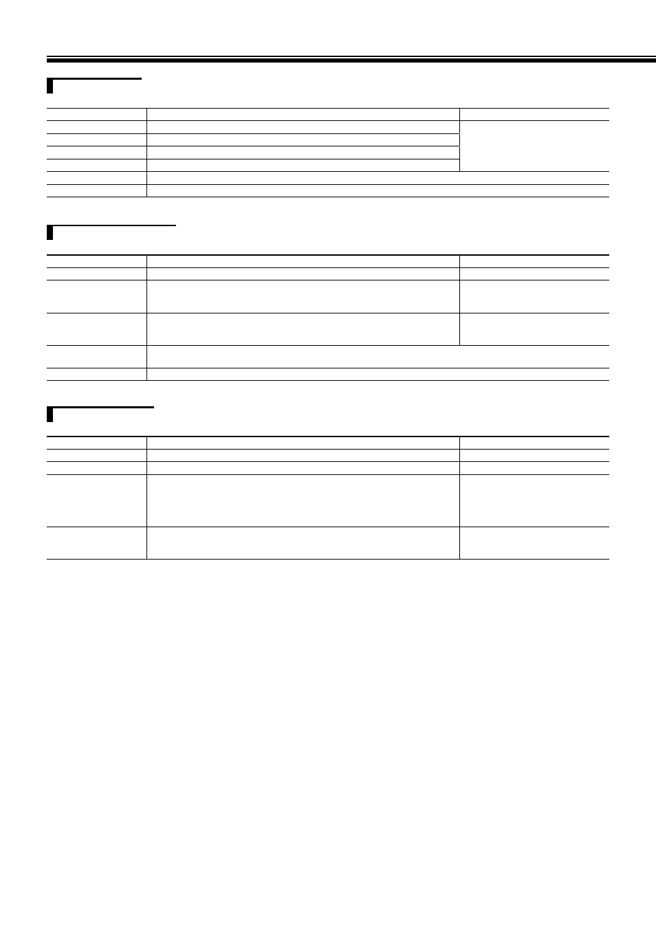
Menu Confi guration (cont.)
SIZE/POSI. ADJ.
Adjusts the size and position of the picture.
Item
To do
Setting value
H SIZE
*1
Adjust the horizontal picture size.
Setting value varies depending on
the signals.
H POSITION
*1
Adjust the horizontal picture position.
V SIZE
*1
Adjust the vertical picture size.
V POSITION
*1
Adjust the vertical picture position.
sub menu
Display the sub menu which enables you to adjust the items of “SIZE/POSI. ADJ.” while viewing the actual picture.
reset
Restore the default settings for all the items in “SIZE/POSI. ADJ.”
*1
Memorized for each signal format.
WHITE BALANCE SET.
Selects the GAMMA correction value, color temperature and adjusts the drive level and cutoff point of each color (R/G/B).
Item
To do
Setting value
COLOR TEMP.
Select the color temperature.
9300K, 6500K, USER
R DRIVE
G DRIVE
B DRIVE
*2
Adjust the drive level of each color (red, green, and blue).
MIN – 000 – MAX (in 256 grades)
R CUT OFF
G CUT OFF
B CUT OFF
*2
Adjust the cutoff point of each color (red, green, and blue).
MIN – 000 – MAX (in 256 grades)
sub menu
Display the sub menu which enables you to adjust the items in “WHITE BALANCE SET.” while viewing the actual
picture.
reset
Restore the default settings for the drive levels and cutoff points of the selected color temperature.
*2
Memorized for each color temperature.
REMOTE SETTING
(
☞ “External Control” on pages 18 to 21)
Settings for the external control
Item
To do
Setting value
SERIAL TYPE
Select the input terminal used for external control by serial communication.
RS232C, RS485
PARALLEL TYPE
Select the external control method for the MAKE/TRIGGER terminal.
MAKE, TRIGGER, SET
PIN1
PIN2
PIN3
PIN4
PIN5
Assign the control functions to the pins of the MAKE/TRIGGER terminal.
Assign a function to each pin terminal by selecting “SET” in “PARALLEL
TYPE” mentioned above.
•
☞ “Functions controlled by the
MAKE/TRIGGER system” on page
19
PIN6
PIN7
PIN8
The functions are assigned for “PIN6” – “PIN8” and you cannot change the
assignment of these functions.
☞ “Using the MAKE/TRIGGER
system” on page 18