Rear panel connectors to camera, Serial-1, -2, Dip switch – JVC RM-P2580 User Manual
Page 23
23
The electrical standards applied to the SERIAL-1 and SERIAL-
2 connectors can be switched between RS-232C and RS-422A
using pins 7 and 8 of the rear panel DIP switch.
4. CONNECTIONS
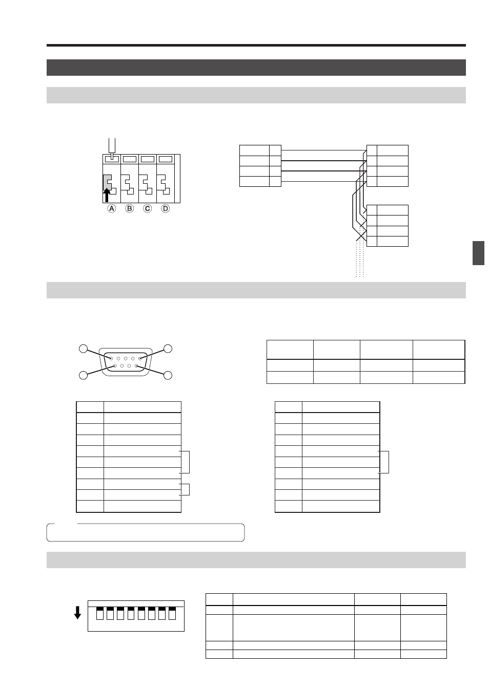
REAR PANEL CONNECTORS
TO CAMERA
Connection to control the camera. (The RM-P2580 is compatible with a TK-C675B camera.)
Communication is carried out by MULTIDROP FULL DUPLEX (RS-485, FULL DUPLEX).
SERIAL-1, -2
Connect a frame switcher, etc.
(D-sub 9-pin, male connectors)
R X +
R X –
T X +
T X –
A
B
C
D
RM-P2580
CAMERA 1
T X +
T X –
R X +
R X –
T X +
T X –
R X +
R X –
CAMERA 2
Attach or remove each cable by pushing
down and holding each terminal connector,
as shown above.
Hold.
RX+ RX-
TX-
TX+
A
B
C
D
A
B
C
D
5
9
1
6
DIP SW
7
8
Set
Connector
SERIAL-1
SERIAL-2
OFF
RS-232C
RS-232C
ON
RS-422A
RS-422A
Pin No.
Signal Name
1
2
3
4
5
6
7
8
9
NC
RXD (Data input)
TXD (Data output)
DTR (Control output)
GND
DSR (Control input)
RTS (Control input)
CTS (Control output)
NC
Pin No.
Signal Name
1
2
3
4
5
6
7
8
9
NC
RXD- (Data input)
TXD- (Data output)
NC
GND
NC
TXD+ (Data output)
RXD+ (Data input)
NC
Signals when the RS-232C is set
Internally connected.
Internally connected
via a driver.
Signals when the RS-422A/485 is set
Internally connected.
Set the mode and select the electrical standard for the SERIAL connector.
DIP Switch
4
3
1 2
8
7
5 6
ON
(Default: All OFF)
Description
OFF
ON
Pin No.
1
2
|
6
7
8
System mode selection
Cannot be used.
(Ensure that they are set to OFF.)
SERIAL-1 electrical standard selection
SERIAL-2 electrical standard selection
A mode
RS-232C
RS-232C
B mode
RS-422A
RS-422A
Note
Communication speed is 9600 bps.