Camera selection 1, 10 selecting a desired camera, Camera operation details – JVC RM-P2580 User Manual
Page 10: Basic operations
10
Selecting a Desired Camera
2. BASIC OPERATIONS
CAMERA SELECTION
1.
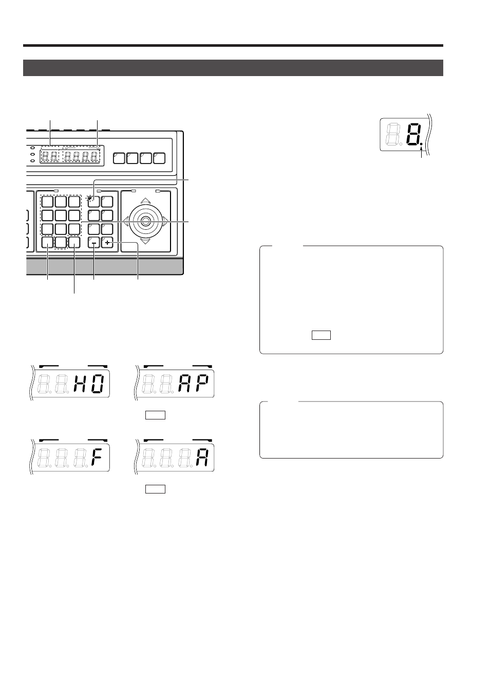
Press the CAMERA button so that the indicator lights up.
2.
Input the camera number using the numeric keys (0 to 9).
The input figure is shown in the
CAMERA display together with
a period after it. (Example: When
“8” is input)
To clear the input figure, press
the CLEAR button.
3.
Press the ENTER button to enter the input camera number.
The video of the selected camera will be output from the
MONITOR OUTPUT connectors on the rear panel.
At this time, the period in the CAMERA display disappears
and the POSITION display shows the camera operation
details (position, fixed camera, AUTO PATROL, AUTO
PAN, etc.).
NOTES
●
When no camera is connected to a camera number,
the camera number is skipped.
●
Be sure to set each camera ID to the same number
as the corresponding VIDEO INPUT connector. Er-
roneous settings may cause operational difficulties.
4.
To view the video of the next camera number, press the +
button. To view the video of the previous camera number,
press the – button.
CLEAR
CLEAR
/HOME
/HOME
7
4
1
8
0
5
2
9
6
3
ENTER
ENTER
AUTO
AUTO
PAN
PAN
OPTION
OPTION
1
OPTION
OPTION
2
CAMERA
CAMERA
POSI-
POSI-
TION
TION
AUTO
AUTO
PATROL
PATROL
AUTO
AUTO
F-1
F-1
F-2
F-2
F-3
F-3
PAN/TILT
PAN/TILT
CAMERA/POSITION
CAMERA/POSITION
CAMERA
CAMERA
POSITION
POSITION
REMOTE CONTROL UNIT
REMOTE CONTROL UNIT
RM-P2580
RM-P2580
ALARM
ALARM
PO
POWER
WER
K
EY LOCK
K
EY LOCK
CAMERA
button
Numeric key
buttons
+ button
CLEAR button
ENTER button
- button
CAMERA display
POSITION display
CAMERA
Period
Camera operation details
NOTES
●
“Camera video” is one of the video signals input to
the VIDEO INPUT connector of this unit or to the frame
switcher.
●
In the case of the B mode in which the output video is
controlled by the frame switcher, in order to allow cam-
era selection from this unit, connect the SERIAL-2
connector on the rear panel of the unit with the RS-
232C connector of the frame switcher. (SW-D7000/
SW-D8000)( REF. : “APPLIED SYSTEM (B MODE)”
on page 22.)
POSITION
POSITION
POSITION
POSITION
Fixed camera display
Position display
(Example with the
home position)
AUTO PATROL
( REF. : Page 15)
AUTO PAN
( REF. : Page 14)