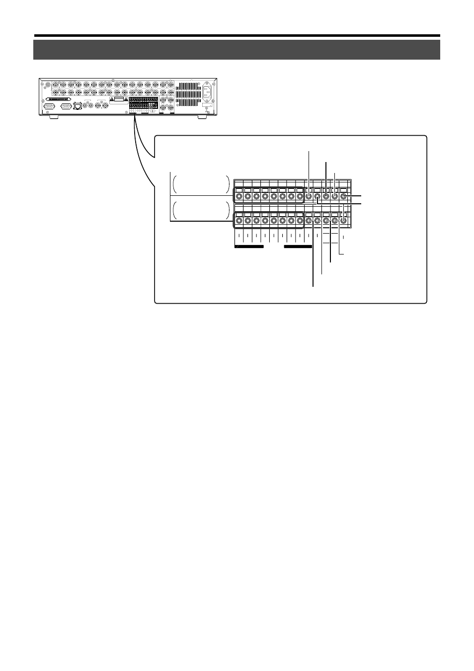
1 [alarm in] terminal (supports channels 1 - 16), 2 [alarm reset] input terminal, 3 [clock reset in] terminal – JVC VR-716E User Manual
Page 10: 4 [series rec in] terminal, 5 [ext rec in] terminal, 6 [com] common ground terminal, 7 [series rec out] terminal, 8 [clock reset out] terminal, 9 [warning out] terminal, 0 [alarm rec out] terminal
10
COM
EXT REC
OUT
REC
SER
IN
OUT
RST
CLK
OUT
WAR
IN
COM
RST
OUT
16
14
12
10
8
6
4
2
15
13
11
9
7
5
3
1
ALARM
1
ALARM IN
2
ALARM RESET
3
CLOCK RESET IN
4
SERIES REC IN
5
EXT REC IN
6
COM
7
SERIES REC OUT
8
CLOCK RESET OUT
9
WARNING OUT
0
ALARM REC OUT
COM
EXT REC
OUT
REC
SER
IN
OUT
RST
CLK
OUT
WAR
IN
COM
RST
OUT
16
14
12
10
8
6
4
2
15
13
11
9
7
5
3
1
ALARM
13 16
9 12
5 8
1 4/ 16
EE OUT
SCSI
RS-232C
UPS
2
1
AUDIO OUT
VIDEO OUT
2
1
LAN
AUDIO IN
VIDEO IN
THRU OUT
1
2
3
4
5
6
7
8
9
10
11
12
13
14
15
16
CAUTION
RISK OF ELECTRIC SHOCK
DO NOT OPEN
AVIS:RISQUE DE CHOC
ELECTRIQ
AC IN
(220V–240V )
SIGNAL GND
1 [ALARM IN] Terminal (Supports Channels 1 - 16)
Terminal that accepts input signals to start alarm or sensor
recording.
2 [ALARM RESET] Input Terminal
Terminal that accepts signals to stop recording during alarm
or sensor recording.
3 [CLOCK RESET IN] Terminal
For connection to a master clock or the [CLOCK RESET
OUT] terminal of other devices. This equipment can be set
to a master clock or the clock of other devices upon the
input of clock reset signals.
The clock in VR-716 will be reset as follows upon the input
of clock reset signals:
• When the value is 29 seconds or less, this will be reset to
00 seconds with the minute value unchanged.
• When the value is 30 seconds and above, this will be
reset to 00 seconds with the minute rounded to the next
higher value.
☞ Page 61 ‘Series Recording Using 2 or More VR-716 Re-
corders’
4 [SERIES REC IN] Terminal
Series recording will start upon the input of [SERIES REC
OUT] signals. This is the terminal that accepts the series
recording signals of other VR-716s when multiple sets of
VR-716 are used.
☞ Page 61 ‘Series Recording Using 2 or More VR-716 Re-
corders’
Getting Started (continued)
Names and Functions (Signal In/Out Terminal)
5 [EXT REC IN] Terminal
Starts recording automatically upon receiving external sig-
nals when the “EXT REC MODE” is set as “TRIGGER” or
“MANUAL”.
☞ Page 25 ‘OPERATION/EXT REC Menu’
☞ Page 61 ‘Activation of Recording Via External Signals’
6 [COM] Common Ground Terminal
This is a common ground terminal. For connection to the
signal ground terminal of other devices.
7 [SERIES REC OUT] Terminal
Outputs signals when the remaining hard disk space is 1 %
or less.
However, there will be no signal output in the following cir-
cumstances:
• When the “SERIES REC” item is set as “OFF” in the menu.
☞ Page 25 ‘OPERATION/EXT REC Menu’
☞ Page 61 ‘Series Recording Using 2 or More VR-716 Re-
corders’
8 [CLOCK RESET OUT] Terminal
Terminal for output of clock reset signals. Signals are out-
put in the following cases:
When the internal clock of VR-716 turns 00:00 or 12:00.
☞ Page 61 ‘Series Recording Using 2 or More VR-716 Re-
corders’
9 [WARNING OUT] Terminal
Outputs signals during hard disk malfunction or error oc-
currence. (
☞ Page 105)
0 [ALARM REC OUT] Terminal
Outputs signals when VR-716 is in the Alarm Recording or
Sensor Recording mode.
(Rear)
CAMERA 1, 3, 5,
7, 9, 11, 13, 15
CAMERA 2, 4, 6,
8, 10, 12, 14, 16