For the relay terminals and 16 awg (1.5 mm – J. T. Eaton Liquid-Cooled Drives LCX9000 User Manual
Page 64
LCX9000 Liquid-Cooled Drives User Manual
4-6
For more information visit: www.EatonElectrical.com
MN04005001E
January 2007
Control Cables
The control cables should be at least 20 AWG (.5 mm
2
) screened multicore cables, see Table
3-1. The maximum terminal wire size is 14 AWG (2.5 mm
2
) for the relay terminals and 16
AWG (1.5 mm
2
) for other terminals.
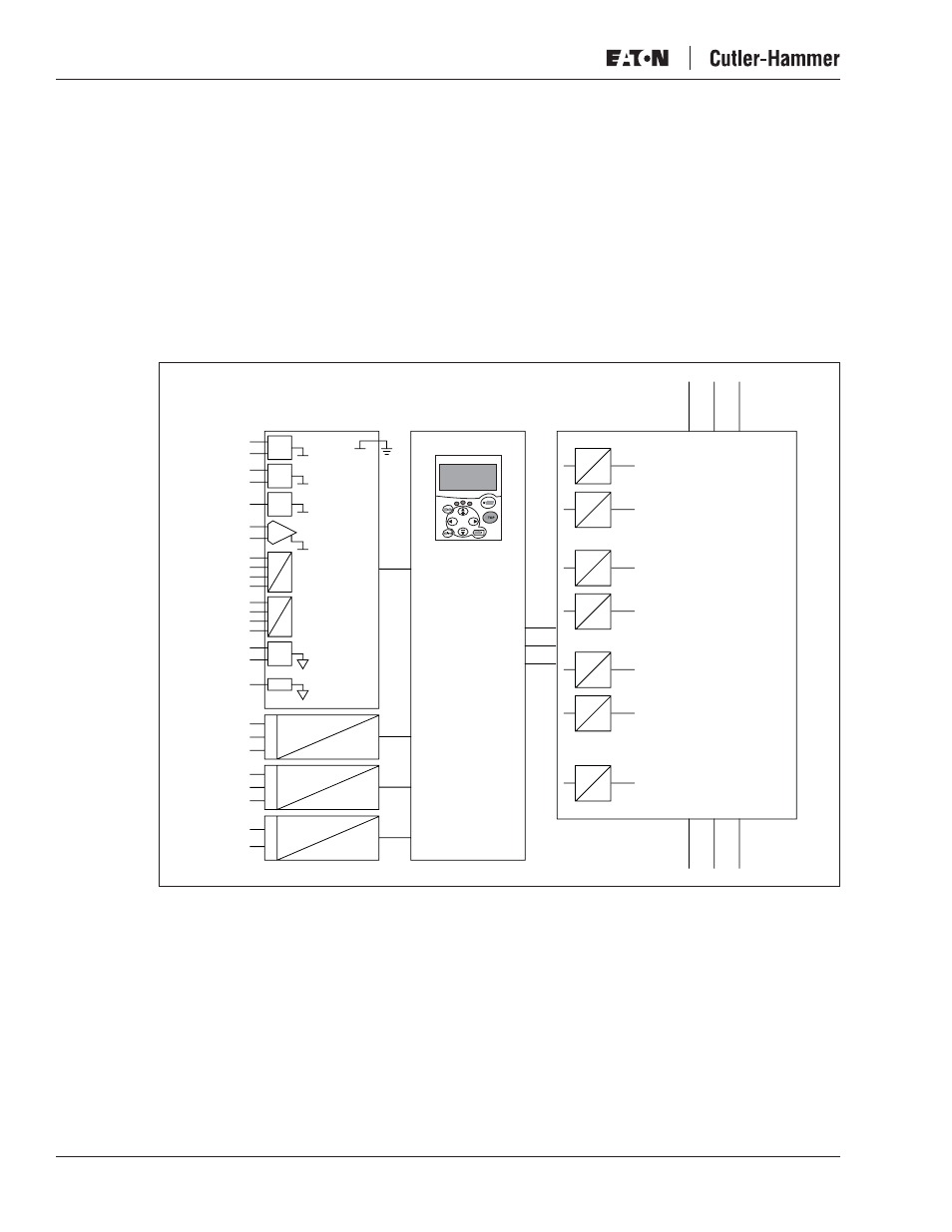
Galvanic Isolation Barriers
The control connections are isolated from the mains potential and the GND terminals are
permanently connected to ground. See Figure 4-9.
The digital inputs are galvanically isolated from the I/O ground. The relay outputs are
additionally double-isolated from each other at 300V AC (EN-50178).
Figure 4-9: Galvanic Isolation Barriers
RO1/1
Control I/O
Ground
Digital Input
Group A
Digital Input
Group A
Analog
Output
Digital
Output
RO1/2
RO1/3
RO2/1
RO2/2
RO2/3
TI1+
TI1–
AI1
+10Vref
+24V
GND
GND
AI2+
AI2-
DIN1...
DIN3
CMA
DIN4...
DIN6
CMB
AO1+
AO2-
DO1
Control
Panel
Gate Drivers
Control
Board
Power
Board
U
V
W
L1
L2
L3