Lcx9000 liquid-cooled drives user manual – J. T. Eaton Liquid-Cooled Drives LCX9000 User Manual
Page 121
LCX9000 Liquid-Cooled Drives User Manual
MN04005001E
For more information visit: www.EatonElectrical.com
B-5
January 2007
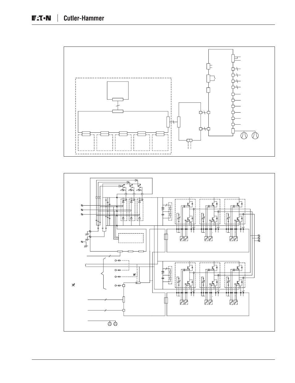
Figure B-8: Main Circuit and Control Diagram, CH63, Control
Figure B-9: Main Circuit and Control Diagram, CH72
Control Board
Option
Board
Option
Board
Option
Board
Option
Board
Option
Board
Control
Panel
X1
9
X7
X2
(Slot A)
X3
(Slot B)
X4
(Slot C)
X5
(Slot D)
X6
(Slot E)
X1
37
X1
VB00228
X2
H1...H7
+24V
GND X3
Ext +24V
2
1
H1...H7
7
2
X10
+24V
X1
+24V
WL H13
WH H12
VL H11
VH H10
UL H9
UH H8
X11
X15
21
22
23
25
26
X9 VB00451
X6
1
2
3
+24V
Charge
Feedback
Charge
Relay
Fan
Control
ASIC
Board
10
10
10
X5
X4
X3
X2
Opto
Adapter
Board
Control Unit
DC+
DC-
Driver U/X6
5
RECT/X13
Driver V/X2
Driver W/X6
Driver U/H15
Driver U/H16
Driver V/H2
Driver W/H16
Driver V/H4
Driver W/H15
Module 2
Internal Fans
DC+
K1
K2
X10
X9
X1
X2
X3
X41
X4
500/VB00459
690/VB00460
Rectifier Board
Mains Voltage
Supervision
X13
5
X6
X50
PE
L3
L2
L1
X8
X11
X12
K3
3
2
DC-
X1
X20
Driver
Board
VB00487
X13...X15
H4...H9
UH...WL
Internal
Fans
X1...
X5
500/VB00526
690/VB00524
Measurement
Board 1
5
Te
rm
U
1
U_Hi
U_Lo
I_U1
Te
rm
V
1
V_Hi
V_Lo
I_V1
5
Te
rm
W
1
Te
rm
U
1
Te
rm
V
1
Te
rm
W
1
W_Hi
W_Lo
I_W1
5
W/T3
V/T2
U/T1
ASIC/
X3...X5
ASIC/
H8...H13
ASIC/
X1
ASIC/
X6
ASIC/
X2
With SPU-024
option only
SP+
SP-
SPP
SPF1
X1/+: Connected to B+
if SPU-024 not in use
6
3 x 10
Module Right Side
3
2
X1...
X5
X3...
X7
X8...
X12
500/VB00525
690/VB00523
Measurement
Board 2
5
U_Hi
U_Lo
I_U1
V_Hi
V_Lo
I_V1
5
W_Hi
W_Lo
I_W1
5
Module Left Side