Lcx9000 liquid-cooled drives user manual – J. T. Eaton Liquid-Cooled Drives LCX9000 User Manual
Page 63
LCX9000 Liquid-Cooled Drives User Manual
MN04005001E
For more information visit: www.EatonElectrical.com
4-5
January 2007
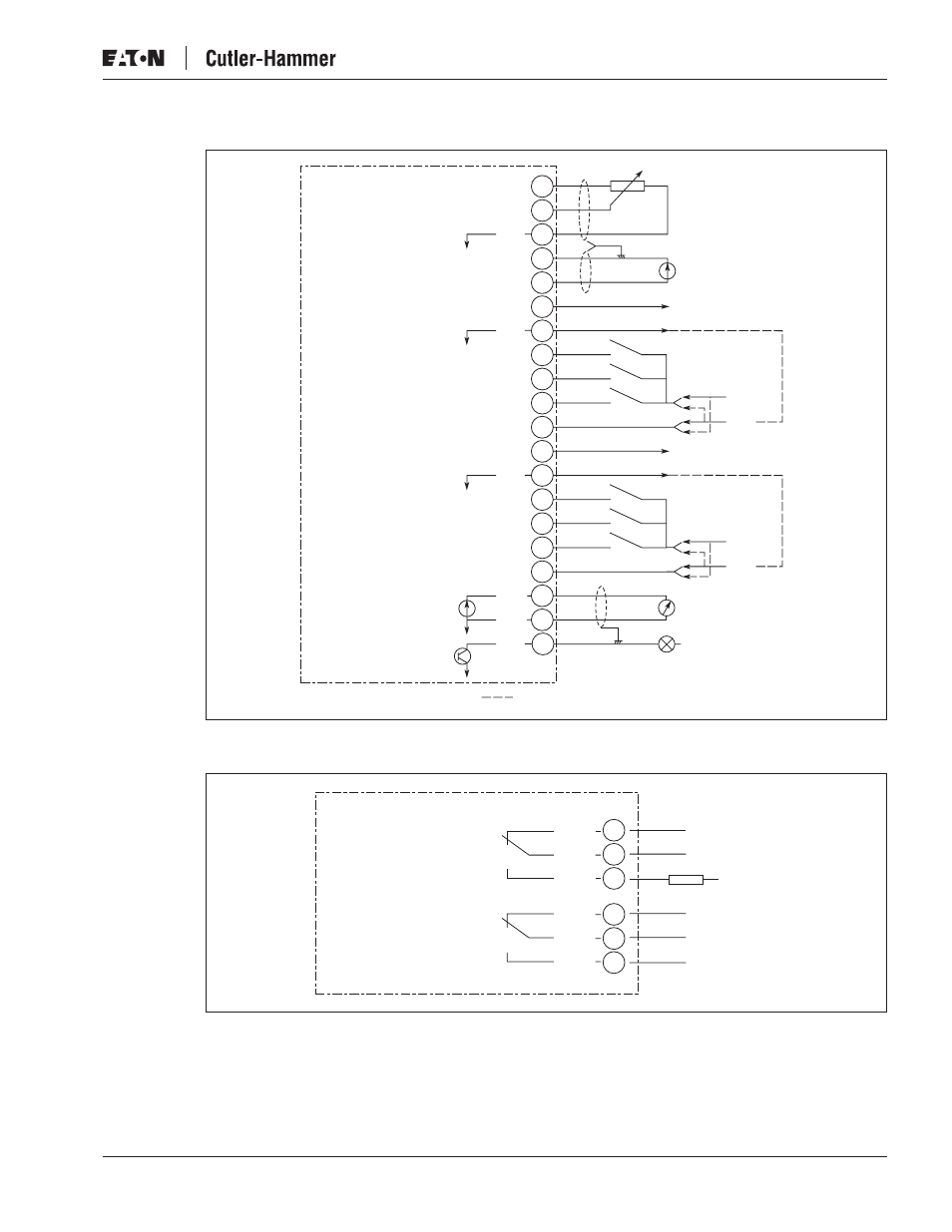
Figure 4-7: General Wiring Diagram of the Basic I/O Board (OPT-A9)
Figure 4-8: General Wiring Diagram of the Basic Relay Board (OPT-A2)
20
19
18
17
16
15
14
13
12
11
10
9
8
24V
GND
[x
[x
24V
GND
+
0 (4)/20 mA
RC<500
Ω
U<+48V
I<50 mA
Input Reference
(Voltage)
Input Reference
(Current)
Indicates Connections for Inverted Signals
Control Voltage Output
Basic I/O Board A9
AI1+
+10Vref
24Vout
24Vout
2
3
4
5
6
7
GND
AI2+
AI2-
GND
DIN1
DIN2
DIN3
CMA
DIN4
GND
DIN5
DIN6
CMB
AO1+
DO1
AO1-
1
26
25
24
23
22
21
RO1/1
RO1/2
RO1/3
RO2/1
RO2/2
RO2/3
R
L
Switching:
<8A / 24V DC
<2kVA / 250V AC
<0.4A / 125V DC
Continuously
<2 Arms
AC / DC
Basic Relay Board OPT-A2