Lcx9000 liquid-cooled drives user manual – J. T. Eaton Liquid-Cooled Drives LCX9000 User Manual
Page 123
LCX9000 Liquid-Cooled Drives User Manual
MN04005001E
For more information visit: www.EatonElectrical.com
B-7
January 2007
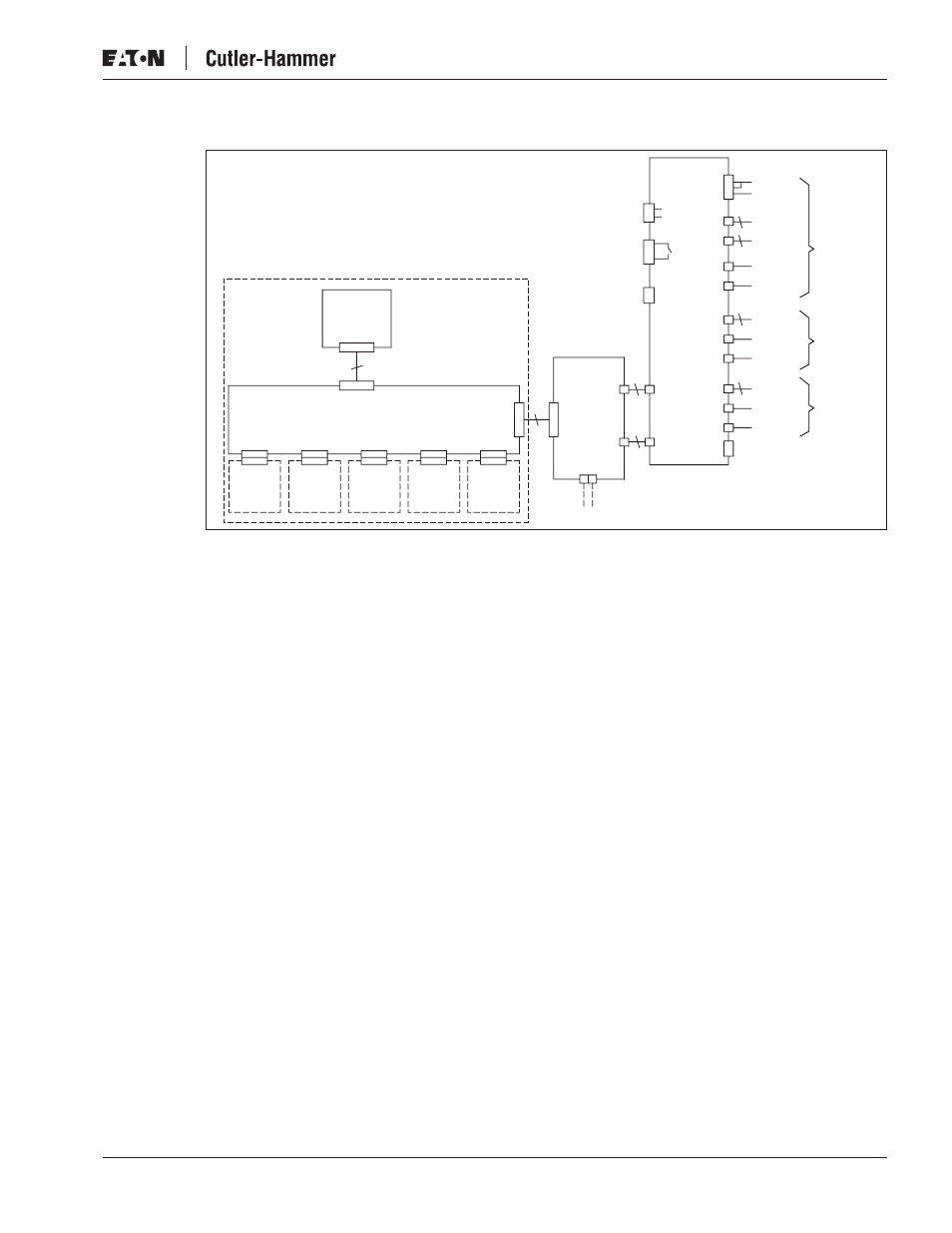
Figure B-12: Main Circuit and Control Diagram, CH74, Control
Control Board
Option
Board
Option
Board
Option
Board
Option
Board
Option
Board
Control
Panel
X1
9
X7
X2
(Slot A)
X3
(Slot B)
X4
(Slot C)
X5
(Slot D)
X6
(Slot E)
X1
37
X1
VB00228
X2
H1...H7
+24V
GND X3
Ext +24V
2
1
H1...H7
7
2
X10
+24V
X1
+24V
WL H13
WH H12
X5
VL H1
VH H10
X4
X11
X15
21
22
23
25
26
X9 VB00451
X6
1
2
3
+24V
DEVA
Charge
Relay
Fan
Control
ASIC
Board
10
10
10
UL H9
UH H8
X3
X2
Opto
Adapter
Board
Control Unit
DC+
DC-
Phase
Module U
Phase
Module V
Phase
Module W
Driver/H2
Driver/X1
5
RECT/X13
Driver/H4
Driver/X1
Driver/H2
Driver/H4
Driver/H4
Driver/X1
Driver/H2