Index of parts and controls – JVC GVT0141-003A User Manual
Page 51
5
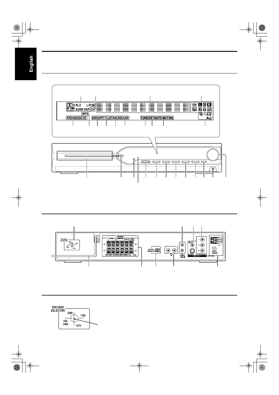
Index of parts and controls
The numbers in the figures indicate the pages where the details of the parts are described.
Front panel (center unit)
Rear panel (center unit)
Setting the VOLTAGE SELECTOR
Before plugging, set the correct voltage for your area with the
voltage selector on the rear panel of the center unit.
Use a screwdriver to rotate the voltage selector so that the voltage
number the voltage mark is pointing at is the same as the voltage
where you are plugging in the center unit.
Display window
21
36
17
21
17
35 35
36
29
16
16
16
14
Disc tray (inside):
16
Remote sensor:
6
16
14
14
13
17
17
18
18
17
17
13
15
8
9
10
7
See below.
10
10
9
37
Voltage mark
THS1[UXUG]-04start.fm Page 5 Friday, August 20, 2004 1:18 PM
See also other documents in the category JVC Home Theater Systems:
- XV-THA75R (76 pages)
- TH-A85 (68 pages)
- TH-M45 (134 pages)
- TH-A25 (50 pages)
- TH-A25 (48 pages)
- TH-V70R (84 pages)
- TH-A9R (65 pages)
- TH-A10R (68 pages)
- TH-A35 (63 pages)
- SP-WA30 (64 pages)
- TH-S2 (44 pages)
- TH-A5R (1 page)
- DD-8 (60 pages)
- QP-F30ALE (40 pages)
- SP-THS5S (48 pages)
- XV-THBD50 (48 pages)
- DVD DIGITAL CINEMA SYSTEM TH-A30R (64 pages)
- SP-THS55C (100 pages)
- Th-g41 (3 pages)
- TH-M505/TH-M501 (52 pages)
- SP-THG51F (29 pages)
- TH-C6 (48 pages)
- TH-C5 (59 pages)
- SP-PWS77 (46 pages)
- TH-S5 (48 pages)
- RX-ES9SL (45 pages)
- XV-THV70R (84 pages)
- XV-THS7 (48 pages)
- XV-THG31 (28 pages)
- SP-THS11C (43 pages)
- SP-THC3F (44 pages)
- EX-D11 (86 pages)
- TH-D8 (38 pages)
- XV-THG41 (29 pages)
- TH-R3 (100 pages)
- SP-PWA9 (67 pages)
- SP-THS11BF (40 pages)
- SP-THC60F (48 pages)
- TM-A9U (8 pages)
- DLA-RS1 (50 pages)
- SP-THD7S (43 pages)
- SP-THM45S (68 pages)
- XV-THA35 (68 pages)
- TH-S66 (49 pages)
- TH-M508 (52 pages)