J-400 series, Page 10, Figure b control box – Jacuzzi J - 480 User Manual
Page 14
Page 10
J-400 Series
8. Connect wires, color to color, on terminal blocks TB1 and TB3 (Figure C-D,
page
). TIGHTEN SECURELY! All wires must be hooked up securely or
damage could result.
9. Install control box door and reinstall the cabinet side panels.
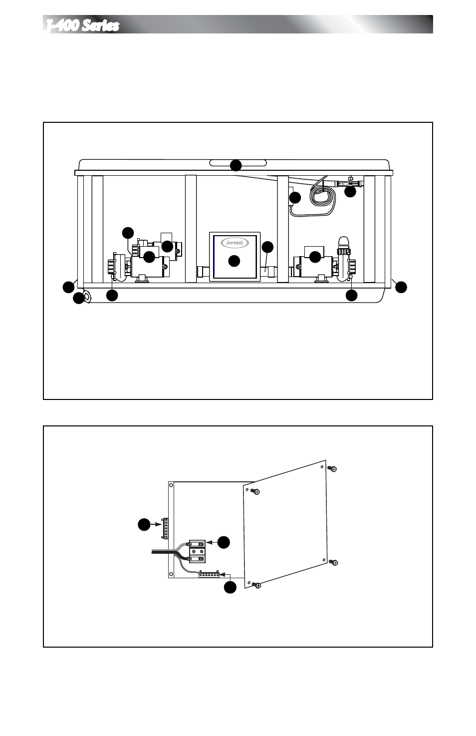
Figure A
Equipment Area
10
4
2
2
Flow
Note: Pump Locations Vary by Model
5
6
6
9
8
7
6
3
1
11
1. Control Box
2. Power Supply Entrance(s)
3. Jet Pump #1
4. Heater
5. Spa Drain Valve
6. Pump Drain Plugs(s)
7. Jets Pump #2
8. Filter/Circulation Pump
9. Optional CD Ozonator (Purchase
Separately)
10. Factory Installed Ozone Injector
11. Control Panel
Figure B
Control Box
TB1
3
2
1
1. Terminal Block
2. Bonding Lug
3. Grounding Terminal
This manual is related to the following products: