0 j-310 convertible circuit diagram (60hz), Page 41 – Jacuzzi 2003+ User Manual
Page 45
Page 41
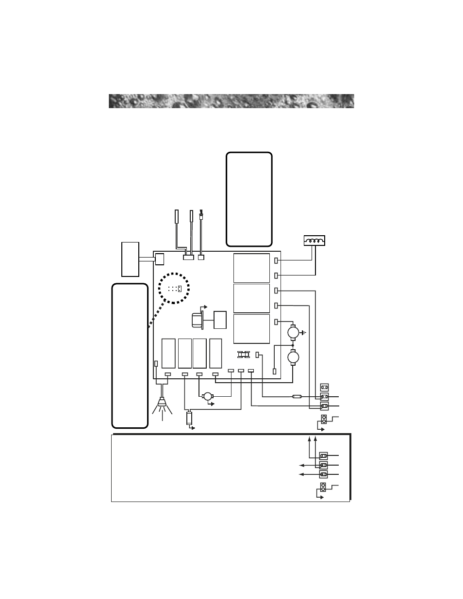
15.0 J-310 Convertible Circuit Diagram (60Hz)
This wiring diagram is used for the J-310 US/Canada 120/240 VAC (60Hz)
convertible power model.
Ozonator
O
3
GRN
TB1
Standard 120 V
AC 3-W
ire Connection
(60 Hz, 1 Phase, 15
A
Service)
Use copper conductors ONL
Y
. Wire size must be
appropriate per NEC and/or local codes.
WHT
WHT
WHT
WHT
WHT
BLK
BLK
RED
BLK
BLK
BLK
BLK
BLK
RED
RED
RED
BLK
3
2
1
Heater
1.0 kW @ 120 V
A
C
4.0 kW @ 240 V
A
C
Flow Switch
Hi-limit/Freeze
Sensor
T
emperature Sensor
J2
J3
F1
20A
250V
SC-20
Circ.
Pump
Main
Pump
Spa Light
T
ransformer
120 V
A
C
J4
BLK
RED
*
GRN
TB1
WHT
BLK
RED
3
2
1
Optional 120/240 V
AC
4-W
ire Convertible
Heater Connection
1. Remove and discard the
factory installed GFCI Cord.
2.
Move RED
*
wire from TB1
position #1 to TB1 position #3
as shown below
.
3. Permanently connect to
the power supply
.
Use
copper conductors ONL
Y
.
W
ire size must be
appropriate per NEC and/or
local codes.
4. If hot tub is to be operated
on 30A
service, make sure
the jumper provided at
location JP1 #1&2 on the
circuit board is installed. If
hot tub is to be operated on
40A
service, remove the
jumper JP1 #1&2 on the
circuit board.
HI
LO
JP1
4
2
3
1
65
87
Logic Jumper Settings (Factory Defaults Shown) JP1 1-2 ON = 15A
Logic (3-wire 120 V
AC operation only)
JP1 1-2 ON = 30A
Logic (4-wire 120/240 V
AC operation only)
JP1 1-2 OFF = 40A
Logic (4-wire 120/240 V
AC operation only)
JP1 7-8 ON = ¡C
T
e
mperature Display
JP1 7-8 OFF = ¡F
T
e
mperature Display
This device complies with Part 15 of the
FCC rules. Operation is subject to the
following two conditions:
1.
This device may not cause harmful
interference.
2.
This device must accept any inteference
received including interference that may
cause undesired operation.
J20
J21
J12
J14
J16
J1
1
J15
J13
J17
J7
J8
J9
J10
J5
J6
Heater IN
Heater OUT
F1*
K1
K2
K3
K4
K5
K7
K8
J1
Control
Panel