Cv-m4+ block diagram, Functions and operations, Basic functions – JAI M4+ CL User Manual
Page 9: Cv-m4, Cl, cv-m7, Block diagram
CV-M4
+
/M4
+
CL, CV-M7
+
/M7
+
CL
- 8 -
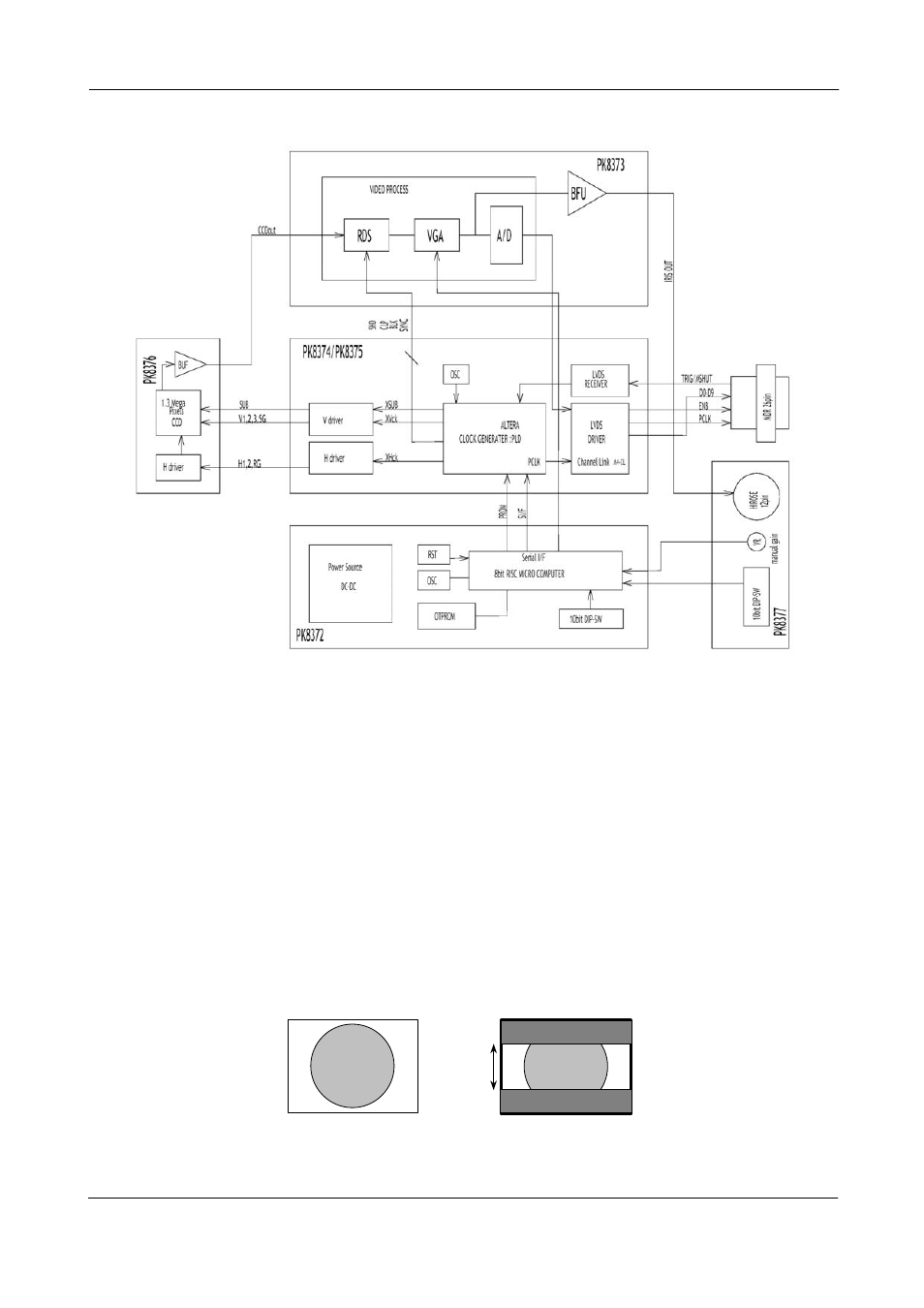
5.5. CV-M4
+
Block Diagram
Fig. 9. Block diagram for the camera
6. Functions and Operations
6.1. Basic functions
The CCD scanning format can be selected between full or partial scanning. With partial scanning
only the vertical central part of the CCD sensor is read out with a higher frame rate. The partial
scan is done by a fast dump read out of the lines in the vertical ccd register down to the top of
the partial image. The partial part of the image is read out with normal speed. The lines below
the partial image is read out and dumped with a high speed. With partial scan the shutter speed
is limited to be shorter than the frame read out time. (SC=1 1/50. SC=2 1/100. SC=3 1/200). In
PWC mode TR=2, there is no limitation.
A minor signal distortion can be expected below highlighted areas, (saturated areas). It is caused
by limitation in the vertical ccd register transfer efficiency at high speed.
Lines shown in partial scans are: 1/2 PS 512 lines. 1/4 PS 256 lines. 1/8 PS 128 lines.
Imaged scene
Partial scanning.
Aspect ratio correct
1380 pixels
1
/2 P
S
,
51
2 p
ixel
s
1/
8 PS,
12
8 p
ixels
1/
4 P
S
,
256
pi
xe
ls
Fig. 10. Partial scanning.