Rs-232c control, Cv-m4, Cl, cv-m7 – JAI M4+ CL User Manual
Page 24
CV-M4
+
/M4
+
CL, CV-M7
+
/M7
+
CL
- 23 -
7.4. RS-232C control
All configuration of the CV-M4
+
camera is done via the RS-232C port. On the 12 pin Hirose
connector, if JP301 is open, or via Camera Link if JP301 is short. The camera can be set up from
a PC running terminal emulator software, or using JAI´s camera control software.
Below is the description of the ASCII based short command protocol.
Communication setting.
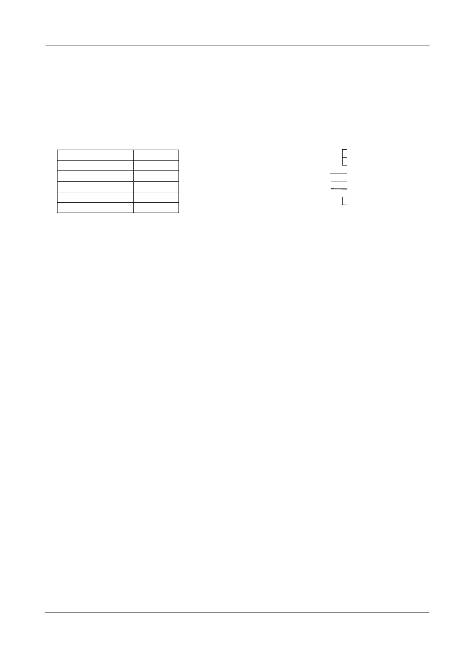
TXD
RXD
GND
1 CD
4 DTR
6 DSR
2 RXD
3 TXD
5 GND
7 RTS
8 CTS
9 CI
9 pin
D-con
PC COM
PORT
CAMERA
TXD
RXD
GND
1 CD
4 DTR
6 DSR
2 RXD
3 TXD
5 GND
7 RTS
8 CTS
9 CI
9 pin
D-con
PC COM
PORT
CAMERA
Baud Rate
9600 bps
Data Length
8 bit
Start Bit
1 bit
Stop Bit
1 bit
Parity None
Xon/Xoff Control None
RS 232C cable
Protocol.
Transmit setting to camera:
NN=[Parameter]
The camera answers:
COMPLETE
To have all communication on the emulator screen, start with:
EB=1
The camera answers:
COMPLETE
Transmit request command to camera:
NN?
The camera answers:
NN=[Parameter]
Transmit the following to have the camera actual setting:
ST?
The camera answers:
A complete list of the current settings
Transmit the following to have a command list:
HP?
The camera answers:
A list with all commands and possible settings
Invalid parameters send to camera:
SH=99
The camera answers:
02 Bad Parameters!!
When the camera is set in “Off Line” (SW1-10 on rear to Local)
NN=[Parameter]
The camera answers:
03 Offline!!