Diagram 2 – Impex IGS-03 User Manual
Page 6
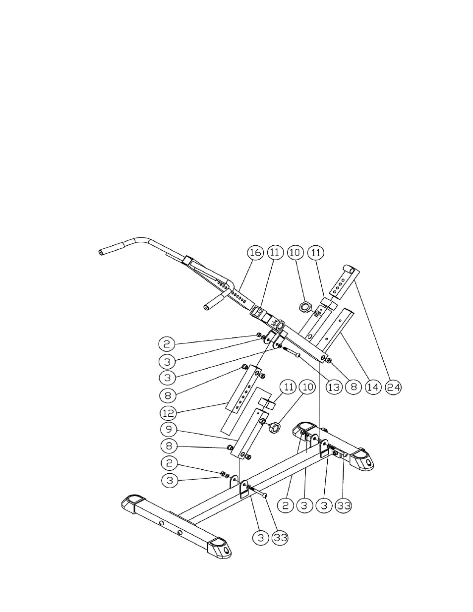
STEP 2 (See Diagram 2)
A.) Attach two Brass Bushings (#8) to the Support Frame (#9). Secure it to the rear
bracket on the Main Frame (#1) with one M10 x 3 ½” Allen Bolt (#33), two
∅
¾”
Washers (#3), and one M10 Aircraft Nut (#2). Do not over tighten the bolt.
B.) Insert the Hyper Adjustment Frame (#12) into the Support Frame (#9). Insert a
Lock Knob (#10) into the selected hole to lock it and obtain the desired height.
C.) Attach two Brass Bushings (#8) to the Akimbo Frame (#14). Secure it to the front
open bracket on the Main Frame (#1) with one M10 x 3 ½” Allen Bolt (#33), two
∅
¾” Washers (#3), and one M10 Aircraft Nut (#2). Do not over tighten the bolt.
D.) Attach two Brass Bushings (#8) to the Hyper Adjustment Frame (#12). Attach it
to the open bracket on the Akimbo Frame (#14). Secure it with one M10 x 3 3/8”
Allen Bolt (#13), two
∅
¾” Washers (#3), and one M10 Aircraft Nut (#2).
E.) Insert the Handle Adjustment Frame (#16) into the top opening on the Akimbo
Frame (#14). Insert a Lock Knob (#10) to selected hole to lock it and obtain the
desired height.
F.) Insert the Foot Adjustment Frame (#24) into the opening on the Akimbo Frame
(#14). Insert a Lock Knob (#10) to secure it.
DIAGRAM 2
5