Step 3 (see diagram 3), Diagram 3 – Impex TC 3000 User Manual
Page 7
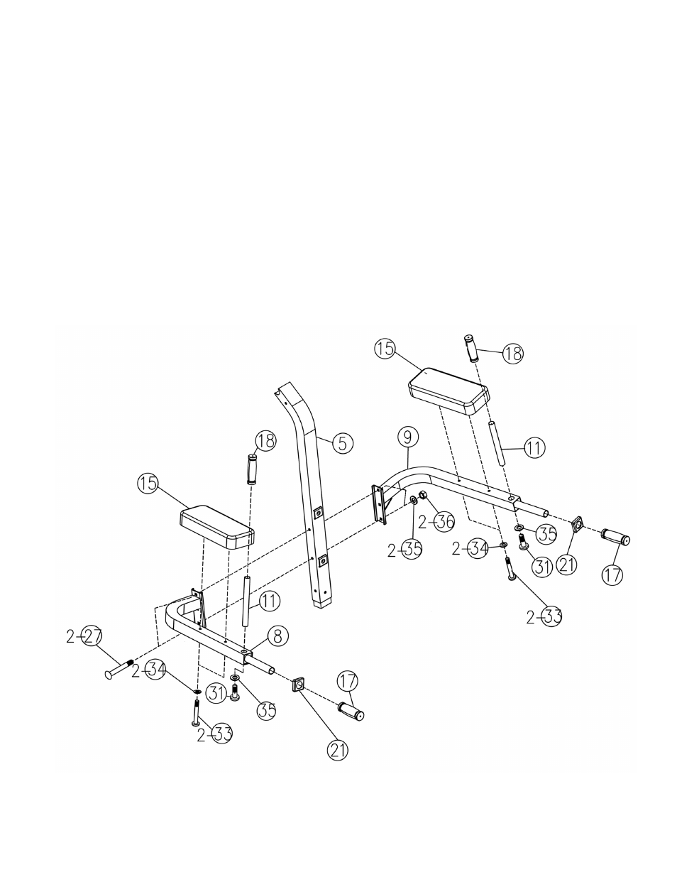
STEP 3 (See Diagram 3)
A.) Attach the Left Dip Support (#8) and Right Dip Support (#9) to the Upper Vertical Frame (#5).
Secure them with two M10 x 3 ¾” Carriage Bolts (#27),
∅
¾” Washers (#35), and M10 Aircraft
Nuts (#36).
B.) Attach two Arm Pads (#15) to Left and Right Dip Supports. Secure each Pad with two M8 x 2
¼” Allen Bolts (#33) and
∅
5/8” Washers (#34).
C.) Insert two Vertical Handles (#11) into the holes on the Dip Supports. Secure them with one
M10 x 5/8” Allen Bolt (#31) and
∅
¾” Washer (#35) underneath each handle. Slide two
∅
1”
Grips (#18) onto the Handles.
E.) Slide two Sleeves (#21) onto the Handles on the Dip Supports. Then slide two
∅
1 3/8” Grips
(#17) onto the handles.
DIAGRAM 3
6
See also other documents in the category Impex Sports and recreation:
- IGS-09 (11 pages)
- SAG-44.1 (10 pages)
- TSA-5682 (14 pages)
- MWM-1840 (29 pages)
- IGS-10 (10 pages)
- TC-6000 (12 pages)
- MWB-715N (12 pages)
- CR 5 (26 pages)
- MD-823 (15 pages)
- PL-43211 (14 pages)
- PL 10510 (12 pages)
- WM-1505 (22 pages)
- PHE1000 (20 pages)
- TSA-5762 (14 pages)
- IGS-5683 (13 pages)
- DBR 400 (7 pages)
- MWM7150 (21 pages)
- DBR 90 (11 pages)
- CG 1400 (24 pages)
- SB 208 (9 pages)
- IGS-02 (10 pages)
- MWB-356 (13 pages)
- AX-PWR7 (21 pages)
- MWB-855 (11 pages)
- TSA-410 (10 pages)
- TSA-41 (7 pages)
- WM 1403 (22 pages)
- DBR 92 (11 pages)
- MARCY TPL-40 (3 pages)
- MSS-1280 (27 pages)
- JD 2 (8 pages)
- PHC-700 (12 pages)
- Gold's Gym WMGG-224 (11 pages)
- MWM 800 (23 pages)
- WM-356 (13 pages)
- EVE-720 (13 pages)
- BF-1201 (22 pages)
- PT 360 (9 pages)
- CB-200 (11 pages)
- Olympic Cage (24 pages)
- EVE-900 (21 pages)
- PT-36 (7 pages)
- PHC-PWR9 (22 pages)
- MWM-1558 (20 pages)
- MWB-4360 (33 pages)