Diagram 2 – Impex TC 3000 User Manual
Page 6
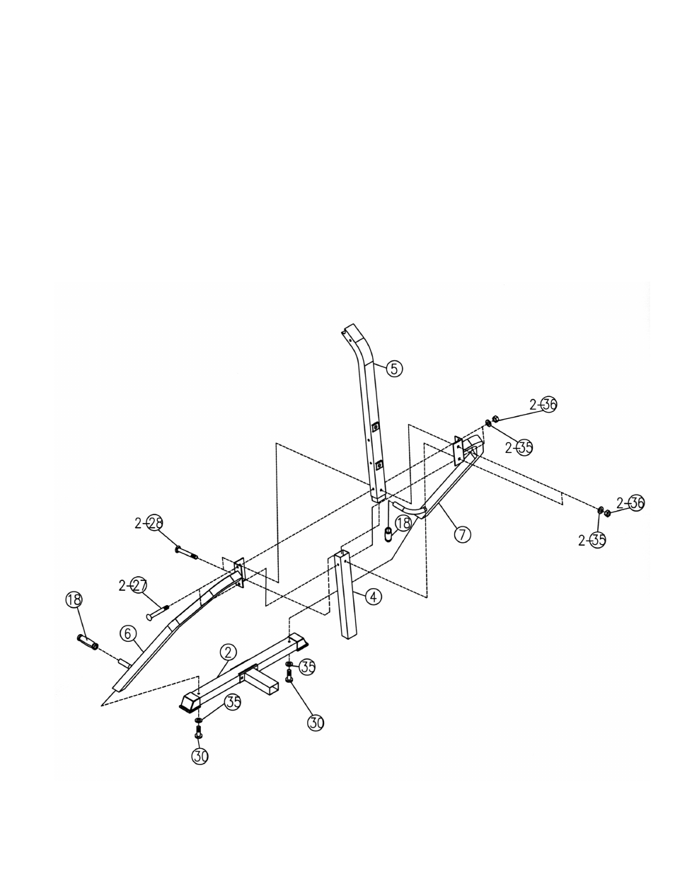
STEP 2 (See Diagram 2)
A.) Attach Left Support Frame (#6) onto the Rear Stabilizer (#2). Secure it with a M10 x 2 ½” Allen
Bolt (#30) and
∅
¾” Washer (#35) from the bottom up. Repeat the same step to install the
Right Support Frame (#7) to the Rear Stabilizer.
B.) Insert the Upper Vertical Frame (#5) into the Lower Vertical Frame (#4). Attach top of the Left
& Right Support Frame (#6) & (#7) to both sides of the Frame. Align the holes and secure the
Support Frames to the Vertical Frame with two M10 x 3 ¾” Carriage Bolts (#27),
∅
¾”
Washers (#35), and M10 Aircraft Nuts (#36). Secure the Vertical Frame with two M10 x 3”
Carriage Bolts (#28),
∅
¾” Washers (#35), M10 Aircraft Nuts (#36).
C.) Slide two Short Grips (#18) onto the curl handles on the Support Frames.
DIAGRAM 2
5
- IGS-09 (11 pages)
- SAG-44.1 (10 pages)
- TSA-5682 (14 pages)
- MWM-1840 (29 pages)
- IGS-10 (10 pages)
- TC-6000 (12 pages)
- MWB-715N (12 pages)
- CR 5 (26 pages)
- MD-823 (15 pages)
- PL-43211 (14 pages)
- PL 10510 (12 pages)
- WM-1505 (22 pages)
- PHE1000 (20 pages)
- TSA-5762 (14 pages)
- IGS-5683 (13 pages)
- DBR 400 (7 pages)
- MWM7150 (21 pages)
- DBR 90 (11 pages)
- CG 1400 (24 pages)
- SB 208 (9 pages)
- IGS-02 (10 pages)
- MWB-356 (13 pages)
- AX-PWR7 (21 pages)
- MWB-855 (11 pages)
- TSA-410 (10 pages)
- TSA-41 (7 pages)
- WM 1403 (22 pages)
- DBR 92 (11 pages)
- MARCY TPL-40 (3 pages)
- MSS-1280 (27 pages)
- JD 2 (8 pages)
- PHC-700 (12 pages)
- Gold's Gym WMGG-224 (11 pages)
- MWM 800 (23 pages)
- WM-356 (13 pages)
- EVE-720 (13 pages)
- BF-1201 (22 pages)
- PT 360 (9 pages)
- CB-200 (11 pages)
- Olympic Cage (24 pages)
- EVE-900 (21 pages)
- PT-36 (7 pages)
- PHC-PWR9 (22 pages)
- MWM-1558 (20 pages)
- MWB-4360 (33 pages)