Miscellaneous connections – Integra DTR-7.3 User Manual
Page 26
26
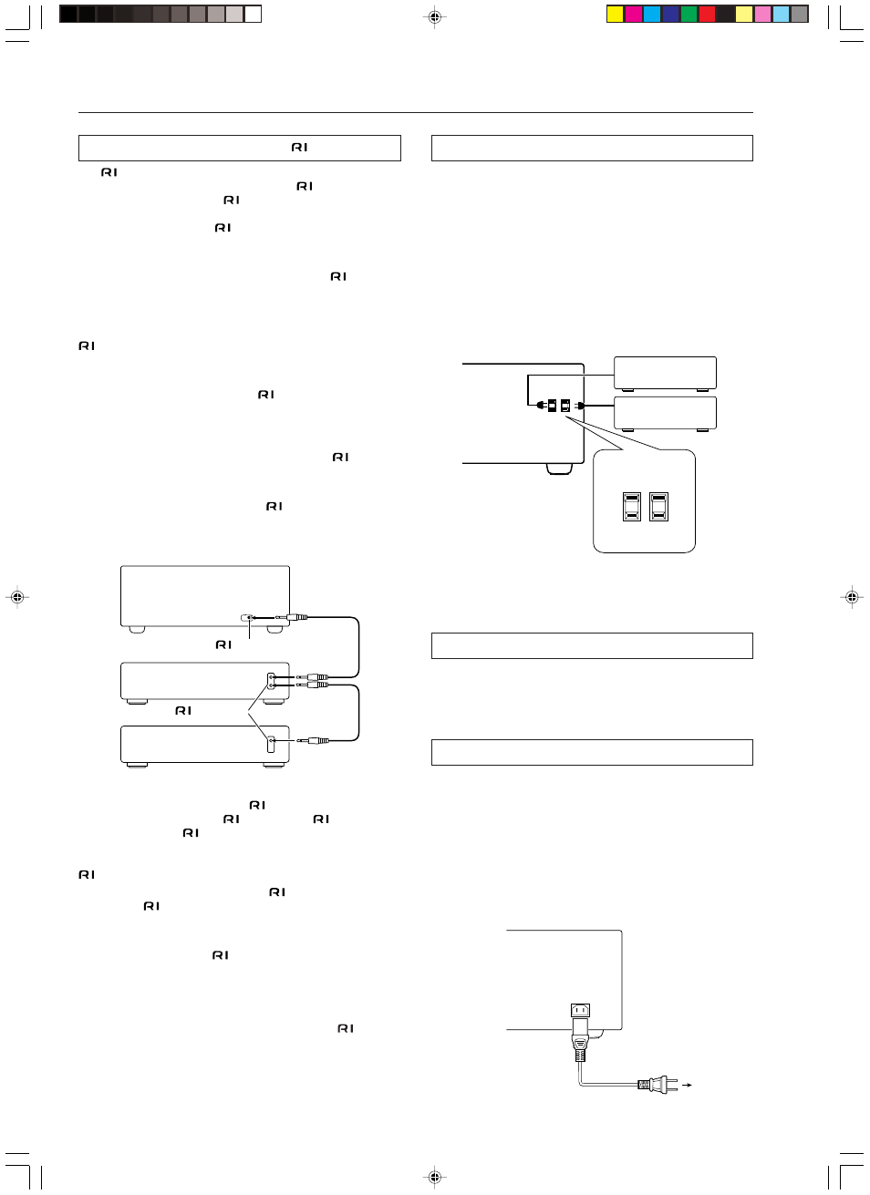
Connecting the power cords from other devices
The DTR-7.3 is equipped with AC mains outlets for connecting the
power cords from other devices so that their power is supplied
through the DTR-7.3. By doing this, you can leave the connected
device turned on and have the STANDBY/ON button on the DTR-
7.3 turn on and off the device together with the DTR-7.3.
The shape, number, and total capacity of the AC outlets may
differ depending on the area of purchase.
Caution:
Make sure that the total capacity of the components connected to the
DTR-7.3 does not exceed the capacity that is printed on the rear
panel (e.g., TOTAL 120W).
RS 232 port
The RS 232 port is to be used in conjunction with an external
controller to control the operation of the DTR-7.3 by using an
external device.
AC INLET
Plug the supplied power cord into this AC INLET and then into the
power outlet on the wall.
• Do not use a power cord other than the one supplied with the
DTR-7.3. The power cord supplied is designed for use with the
DTR-7.3 and should not be used with any other device.
• Never have the power cord disconnected from the DTR-7.3
while the other end is plugged into the wall outlet. Doing so may
cause an electric shock. Always connect by plugging into the
wall outlet last and disconnect by unplugging from the wall
outlet first.
Miscellaneous Connections
Connections for remote control (
)
The
terminal on the DTR-7.3 is for connecting other Integra/
Onkyo components equipped with the same
terminal. When a
component is connected to the
terminal, it can be operated by the
remote controller supplied with the DTR-7.3. In addition, when you
connect a component to the
terminal, you can also perform the
system operations given below.
Power on/ready function
When the DTR-7.3 is in the standby state, if an
-connected
component is turned on, the DTR-7.3 also turns on and the input
source selected at the DTR-7.3 automatically switches to that
component.
Be aware that this function will not work if the power cord for the
-connected component is connected to the AC OUTLET on the
DTR-7.3, or if the DTR-7.3 has already been turned on.
Direct change function
When the play button is pressed at an
-connected component, the
input source selected at the DTR-7.3 automatically changes to that
component.
Power off function
When the DTR-7.3 is placed in the standby state, all
-connected
components are also automatically put into the standby state.
Also, if you press the ON button on the DTR-7.3 remote controller
while the DTR-7.3 is turned on, all
-connected components
(DVD players, CD players, MD recorders, tuners, etc.) are also
turned on.
To connect components using the
terminal, simply connect a
remote control cable from this
terminal to the
terminal of the
other component. An
remote control cable with a 1/8-inch (3.5-
mm) miniature two-conductor plug comes with every cassette tape
deck, compact disc player, MD recorder, and DVD player that has an
terminal.
• When performing operations with
-connected components
using the
system, do not use the remote zone (Zone 2).
• For remote control operation, the audio connection cables must
also be connected.
• If a component has two
terminals, you can use either one to
connect to the DTR-7.3. The other one can be used to daisy chain
with another component.
• With Integra/Onkyo DVD players, you can enter the pre-
program code so that you can operate the DVD player directly
with the remote controller without connecting the
terminals
(see page 65).
AC OUTLETS
AC 120 V 60 Hz
SWITCHED
TOTAL 120W 1A MAX.
USA and Canadian
models
Power cord
(supplied)
To an AC wall
outlet
AC INLET
REMOTE
CONTROL
Ex: Integra/Onkyo CD
player
DTR-7.3
Ex: Integra/Onkyo
cassette tape deck
connector
connector