Impex IGS-07 User Manual
Page 6
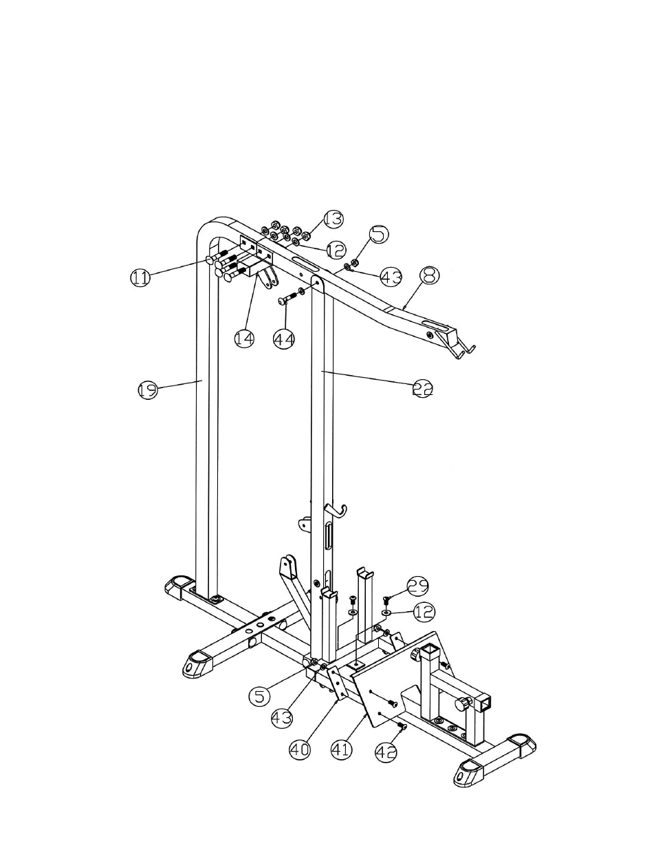
STEP 2 (See Diagram 2)
A.) Align the rear of Upper Frame (#8) to the Rear Vertical Beam (#19). Attach the Top
Socket Assembly (#14) to the joint. Secure it with four M12 x 3 1/8” Carriage Bolts
(#11),
∅
1” Washers (#12), and M12 Aircraft Nuts (#13). Do not tighten the bolts yet.
B.) Place the Upper Frame onto the open bracket on the Front Vertical Beam (#22). Secure
it with one M10 x 3” Allen Bolt (#44), two
∅
¾” Washers (#43), and one M10 Aircraft Nut
(#5). Securely tighten all bolts previously installed.
C.) Attach the Foot Plate Support (#40) to the Base Frame (#45). Secure it with two M12 x
1” Allen Bolts (#29) and
∅
1” Washers (#12).
D.) Attach the Foot Plate (#41) to the Foot Plate Support (#40). Secure it four M10 x 1” Allen
Bolts (#42),
∅
¾” Washers (#43), and M10 Aircraft Nuts (#5).
5
- IGS-09 (11 pages)
- SAG-44.1 (10 pages)
- TSA-5682 (14 pages)
- MWM-1840 (29 pages)
- IGS-10 (10 pages)
- TC-6000 (12 pages)
- MWB-715N (12 pages)
- CR 5 (26 pages)
- MD-823 (15 pages)
- PL-43211 (14 pages)
- PL 10510 (12 pages)
- WM-1505 (22 pages)
- PHE1000 (20 pages)
- TSA-5762 (14 pages)
- IGS-5683 (13 pages)
- DBR 400 (7 pages)
- MWM7150 (21 pages)
- DBR 90 (11 pages)
- CG 1400 (24 pages)
- SB 208 (9 pages)
- IGS-02 (10 pages)
- MWB-356 (13 pages)
- AX-PWR7 (21 pages)
- MWB-855 (11 pages)
- TSA-410 (10 pages)
- TSA-41 (7 pages)
- WM 1403 (22 pages)
- DBR 92 (11 pages)
- MARCY TPL-40 (3 pages)
- MSS-1280 (27 pages)
- JD 2 (8 pages)
- PHC-700 (12 pages)
- Gold's Gym WMGG-224 (11 pages)
- MWM 800 (23 pages)
- WM-356 (13 pages)
- EVE-720 (13 pages)
- BF-1201 (22 pages)
- PT 360 (9 pages)
- CB-200 (11 pages)
- Olympic Cage (24 pages)
- EVE-900 (21 pages)
- PT-36 (7 pages)
- PHC-PWR9 (22 pages)
- MWM-1558 (20 pages)
- MWB-4360 (33 pages)