Diagram 6 – Impex EVE-1500 User Manual
Page 15
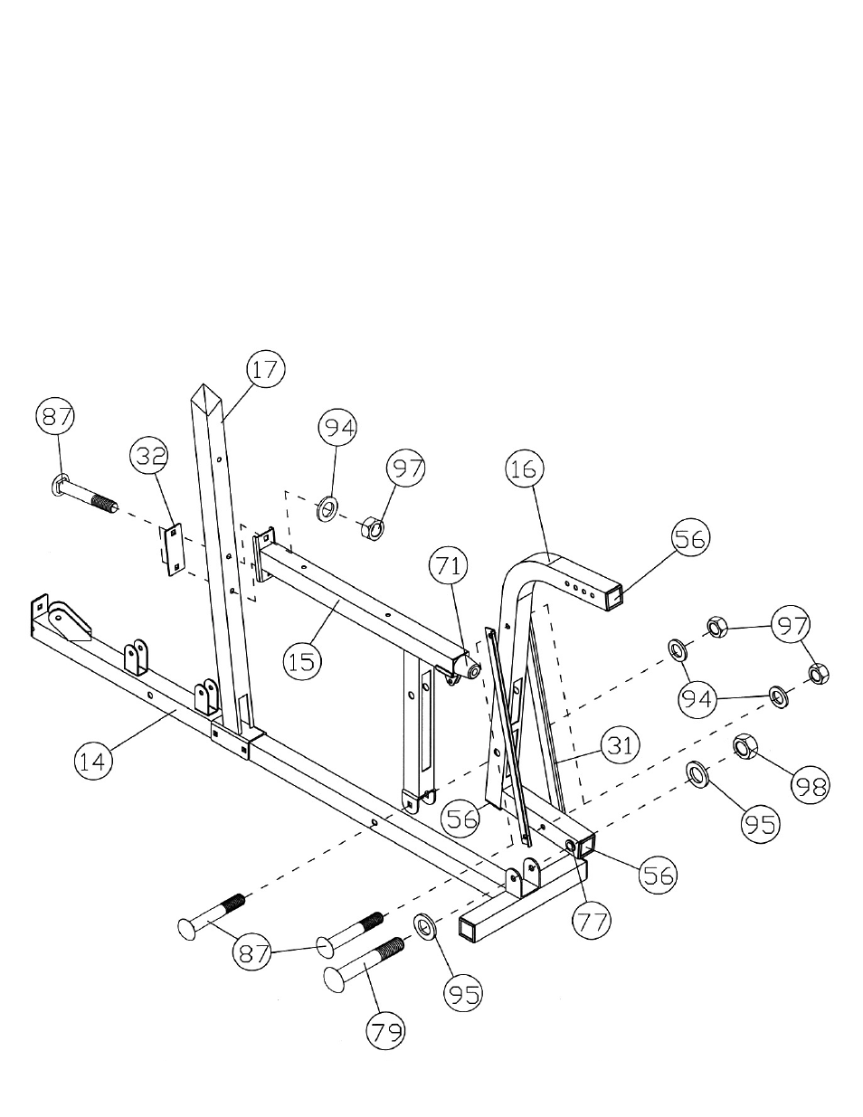
STEP 6 (See Diagram 6)
A.) Attach the Left Seat Support (#15) to the Left Base Frame (#14). Secure it with one M10 x
2 ½”Carriage Bolts (#87), Ø ¾” Washer (#94), and M10 Aircraft Nut (#97).
B.) Attach the Left Seat Support to the Left Vertical Beam (#17). Secure it with two M10 x 2 ½”
Carriage Bolts (#87), one 4 3/8” x 1 ¾” Bracket (#32), two Ø ¾” Washers (#94), and two
M10 Aircraft Nuts (#97).
C.) Attach the Leg Press Frame (#16) to the bracket on the Left Base Frame (#14). Secure it
with one M12 x 3” Allen Bolt (#79), two Ø 1” Washers (#95), and one M12 Aircraft Nut
(#98).
D.) Attach two Leg Press Diagonal Supports (#31) to the Leg Press Frame from both sides.
Secure them with two M10 x 2 ½” Carriage Bolts (#87), Ø ¾” Washers (#94), and M10
Aircraft Nuts (#97). Make sure the Leg Press Frame is able to swivel on its pivot.
E.) Securely tighten all Nuts and Bolts previously installed.
DIAGRAM 6
14
- IGS-09 (11 pages)
- SAG-44.1 (10 pages)
- TSA-5682 (14 pages)
- MWM-1840 (29 pages)
- IGS-10 (10 pages)
- TC-6000 (12 pages)
- MWB-715N (12 pages)
- CR 5 (26 pages)
- MD-823 (15 pages)
- PL-43211 (14 pages)
- PL 10510 (12 pages)
- WM-1505 (22 pages)
- PHE1000 (20 pages)
- TSA-5762 (14 pages)
- IGS-5683 (13 pages)
- DBR 400 (7 pages)
- MWM7150 (21 pages)
- DBR 90 (11 pages)
- CG 1400 (24 pages)
- SB 208 (9 pages)
- IGS-02 (10 pages)
- MWB-356 (13 pages)
- AX-PWR7 (21 pages)
- MWB-855 (11 pages)
- TSA-410 (10 pages)
- TSA-41 (7 pages)
- WM 1403 (22 pages)
- DBR 92 (11 pages)
- MARCY TPL-40 (3 pages)
- MSS-1280 (27 pages)
- JD 2 (8 pages)
- PHC-700 (12 pages)
- Gold's Gym WMGG-224 (11 pages)
- MWM 800 (23 pages)
- WM-356 (13 pages)
- EVE-720 (13 pages)
- BF-1201 (22 pages)
- PT 360 (9 pages)
- CB-200 (11 pages)
- Olympic Cage (24 pages)
- EVE-900 (21 pages)
- PT-36 (7 pages)
- PHC-PWR9 (22 pages)
- MWM-1558 (20 pages)
- MWB-4360 (33 pages)