Intel 8 LAN User Manual
Page 15
15
ICH8—NVM Information Guide
1.4.19
LED 1 Configuration and Power Management (Word 17h)
This field specifies the default values for the LEDCTL register fields controlling the LED1
(LINK_1000) output behaviors and the OEM fields defining the PHY power management
parameters loaded to the PHY_CTRL register.
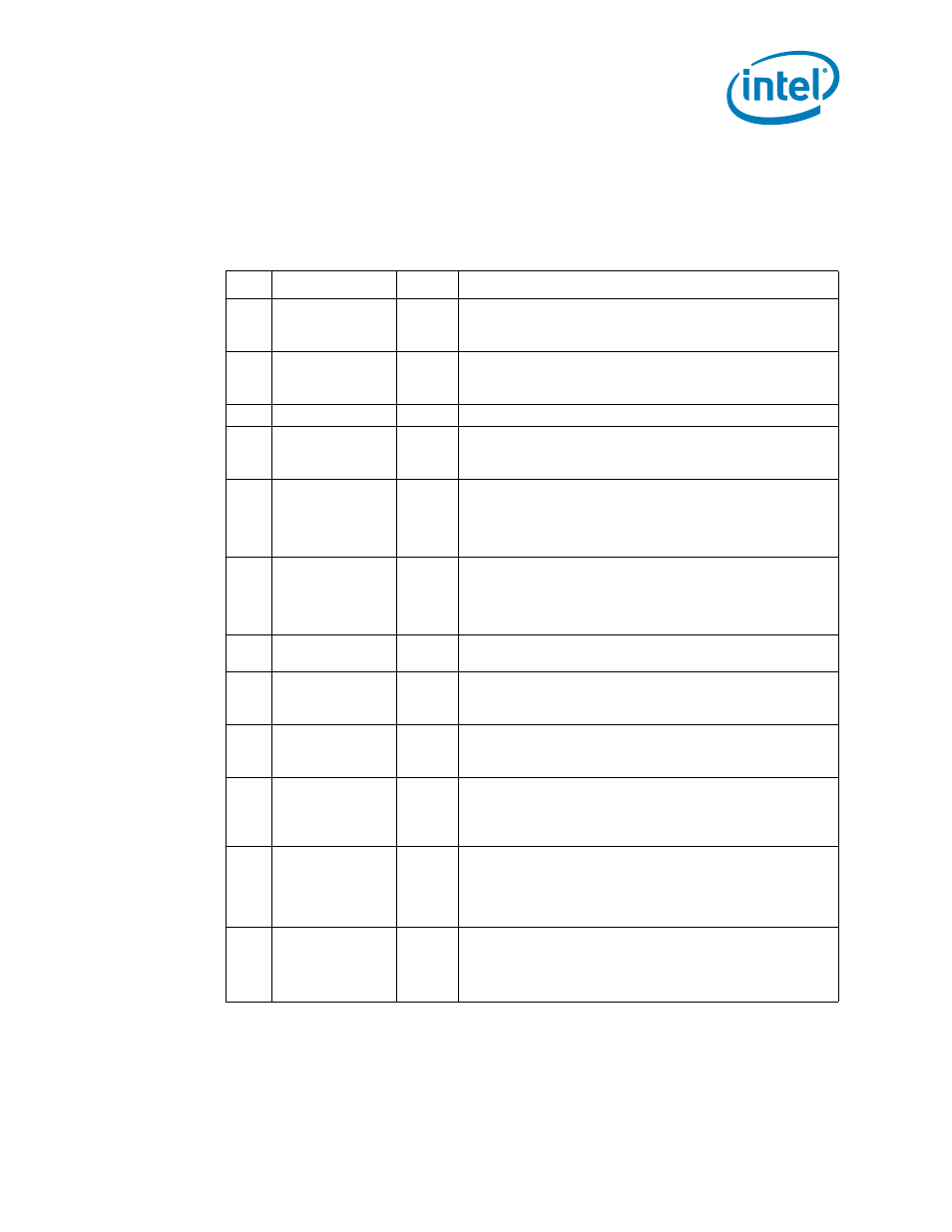
The following table lists the LED modes defined in bits 3:0 of this word.
Table 15.
LED 1 Configuration and Power Management (Word 17h)
Bit
Name
Default
Description
15
B2B Enable
1b
This bit enables Smart Power Down in back-to-back link setup.
0b = B2B disabled.
1b = B2B enabled.
14
GbE Disable
0b
GbE Disable (in all power states)
0b = GbE enabled.
1b = GbE disabled.
13:12
Reserved
00b
These bits are reserved and should be set to 00b.
11
GbE Disable in non-
D0a
1b
GbE Disable (in all power states except D0a)
0b = GbE enabled.
1b = GbE disabled.
10
LPLU Enable in non-
D0a
1b
The Low Power Link Up enables link at the lowest speed supported
by both link partners in non-D0a states. This bit must be set if
LPLU Enable bit is set.
0b = Low Power Link Up is disabled.
1b = Low Power Link Up is enabled in all non-D0a states.
9
LPLU Enable
0b
The Low Power Link Up enables link at the lowest speed supported
by both link partners in all power states. This bit enables a
decrease in link speed in all power states.
0b = Low Power Link Up is disabled.
1b = Low Power Link Up is enabled in all power states.
8
SPD Enable
1b
0b = PHY Smart Power Down mode is disabled.
1b = PHY Smart Power Down mode is enabled.
7
LED1 Blink
0b
This bit indicates the initial value of the LED1_BLINK field.
0b = LED1 is non-blinking (recommended).
1b = LED1 is blinking.
6
LED1 Invert
0b
This bit indicates the initial value of the LED1_IVRT field.
0b = LED1 has an active low output.
1b = LED1 has an active high output.
5
LED1 Blink Mode
0b
This bit defines the LED1 blink mode:
0b = Blink at 200 ms on and 200 ms off.
1b = Blink at 83 ms on and 83 ms off.
This field should be identical to LED0 Blink Mode.
4
Filtered ACT LED
0b
Enable Filtered Activity LED (while operating with the 82562V)
When set to 0b, the activity LED is activated by the PHY.
When set to 1b, the activity LED is driven by Tx activity or Rx
traffic that match any of the MAC's MAC addresses.
For the 82566, this bit is reserved and should be set to 0b.
3:0
LED1 Mode
0111b
These bits represent the initial value of the LED1_MODE field,
which specifies the event, state, or pattern displayed on LED1
(LINK_1000) output.
defines the values for LED1 Mode.
A value of 0111b indicates that a 1000 Mb/s link is established and
maintained.