Impex MWB-9000 User Manual
Page 18
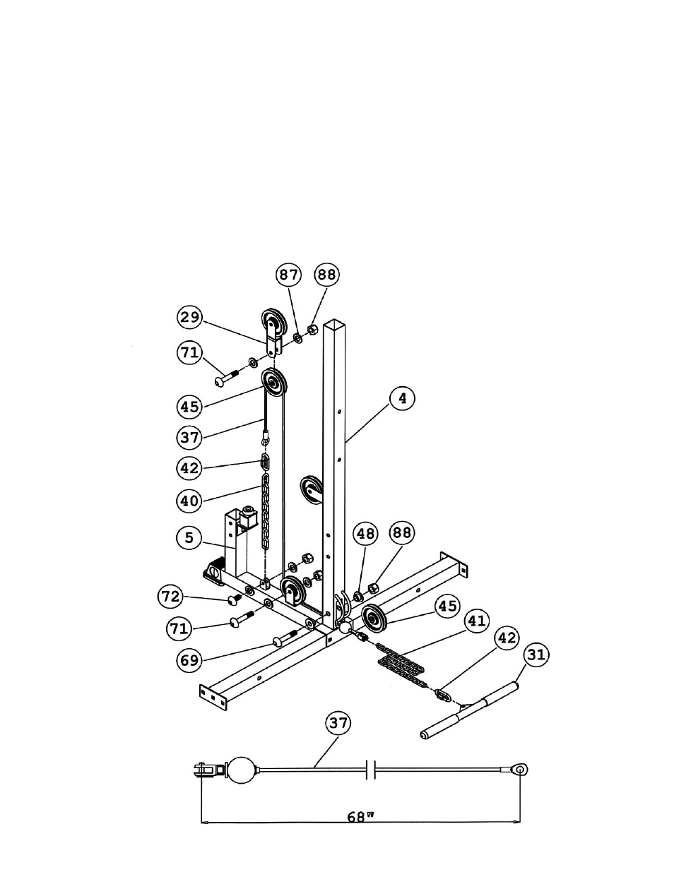
STEP 9 (See Diagram 9 & Cable Loop Diagram)
A.) Attach the 68” Lower Cable (#37) to the opening on the bottom of Middle Vertical
Frame (#4). Attach a Pulley to the opening. Secure it with one M10 x 2 ½” Allen Bolt
(#69), two Long Pulley Bushings (#48), and one M10 Aircraft Nut (#88).
B.) Draw the Cable underneath the Pulley to the open bracket on the Rear Base Frame
(#5). Install a Pulley to the bracket.
C.) Draw the Cable around the Pulley then upward to the Double Floating Pulley
Bracket (#29) previously installed in Step-8. Install another Pulley.
D.) Draw the Cable around the Pulley then down to the open bracket on the Rear Base
Frame. Connect the end of the Cable to a Short Chain (#40) using a C-clip (#42).
Secure the Short Chain to the bracket with one M10 x 1 3/8” Allen Bolt (#72), two Ø
¾” Washers (#87), and one M10 Aircraft Nut (#88). Adjust the tension of the Cable
Loop System by adjusting the length of the Short Chain.
E.) Connect a Long Chain (#41) to the U-shaped Connector at the end of the Cable.
Connect the Shiver Bar (#31) to the Long Chain using a C-clip (#42).
17