Impex MWB-9000 User Manual
Page 17
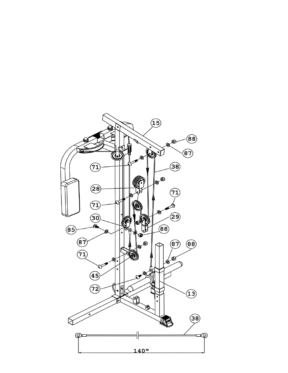
STEP 8 (See Diagram 8 & Cable Loop Diagram)
A.) Attach one end of the 140” High-Low Cable (#38) to the bracket on the Sliding Weight Post
(#13). Secure it with one M10 x 1 3/8” Allen Bolt (#72), two Ø ¾” Washers (#87), and one
M10 Aircraft Nut (#88).
B.) Draw the Cable upward to the open bracket underneath the Lat Bar Frame Bracket (#15).
Install another Pulley.
C.) Draw the Cable around the Pulley then downward. Attach the Cable to a Double Floating
Pulley Bracket (#29). Install a Pulley to the upper bracket.
D.) Draw the Cable around the Pulley and upward to the Angled Floating Pulley Bracket (#28)
previously installed in Step-6. Install another Pulley.
E.) Draw the Cable around the Pulley then downward to the open bracket on the back of the
Middle Vertical Frame (#4). Install another Pulley.
F.) Draw the Cable around the Pulley then upward to the Single Floating Pulley Bracket (#30)
previously installed in Step-7. Secure the end of the Cable to the bracket with one M10 x 1”
Allen Bolt (#85), two Ø ¾” Washers (#87), and one M10 Aircraft Nut (#88).
16