Meyer Sound 600-HP User Manual
Page 32
26
CHAPTER 7
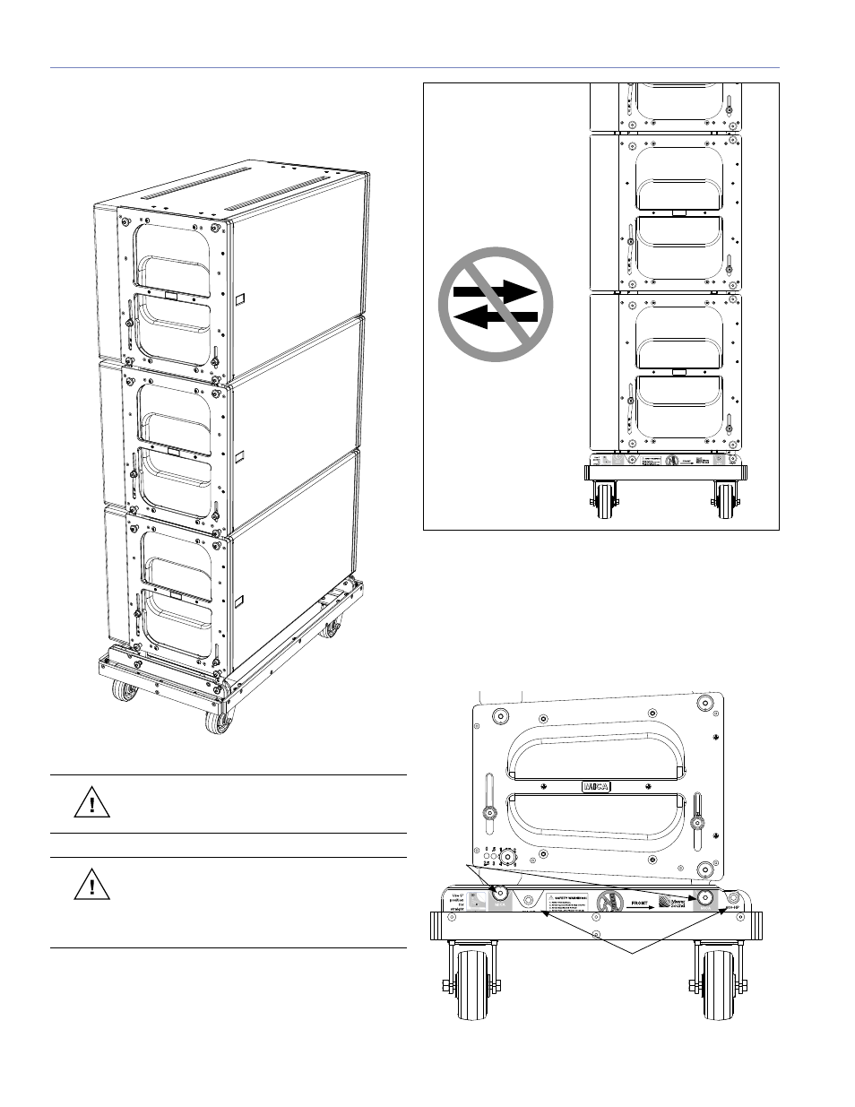
Whether you’re deploying or striking an array, the MCF-
MICA can temporarily support its weight — making it easy
to assemble or disassemble the array in stacks of up to
three 600-HPs.
Figure 7.12. 600-HPs on the MCF-MICA caster frame
CAUTION:
Do not exceed three 600-HP sub-
woofers high to avoid tipping over the stack.
CAUTION:
Avoid moving the 600-HP stack in
the front-to-back direction of the subwoofers
(the long side); always move the stack sideways to
avoid tipping it over.
MG-MICA REAR LINK
Maximum Downtilt
MG-MICA
MG-MICA REAR LINK
Maximum Uptilt
MG-MICA FRONT LINK
Maximum Uptilt
Stowed
Position
Stowed
Position
MG-MICA FRONT LINK
Maximum Downtilt
MICA / 600-HP
REAR LINK
Ground-Stacked
Position
FRONT
MICA / 600-HP
FRONT LINK
Ground-Stacked
Position
1. Always use two quick release pins on each MG-MICA link.
2. DO NOT use ground-stack holes for flying points.
SAFETY WARNINGS!
Figure 7.13. The 600-HP stack should only be moved sideways when being
transported on the MCF-MICA caster frame
In order to transport stacks of 600-HP subwoofers as safely
as possible, the MCF-MICA has two positions — one for
the 600-HP and one for MICA. The 600-HP position allows
the stack to have its center of gravity as close as possible
to the center of the caster frame.
�����������������
����������������
�������
�����������������
��������������
������������������
��������������
������
��������
������
��������
������������������
����������������
��������������
���������
���������������
��������
�����
��������������
����������
���������������
��������
����������������������������������������������������������
���������������������������������������������������
�����������������
MICA
positions
600-HP
positions
Figure 7.14. 600-HP and MICA positions on the MCF-MICA