Ground-stacked – Meyer Sound 600-HP User Manual
Page 29
23
CHAPTER 7
This rigging capability allows all of the 600-HPs to be posi-
tioned at 0 degrees in relation to each other and to the MG-
MICA grid, while introducing the desired angle to the MICA
array using the GuideALinks on the lowest 600-HP enclo-
sure — without needing to adjust the angle of the remaining
600-HPs or the MG-MICA grid.
Table 7.3. 600-HP Link Positions to MICA (flown)
Rear
Front
Angle for MICA below
-3
+3
6° downtilt
0
+3
3° downtilt
0
0
0°
3
0
3° uptilt
6
0
6° uptilt
9
0
9° uptilt
12
0
12° uptilt
15
0
15° uptilt
-3
+0
+3
0
+0
+0
+3
0
+0
-3
0
3
6
9
12
15
Figure 7.5. 600-HP to MICA flown configuration maximum angles
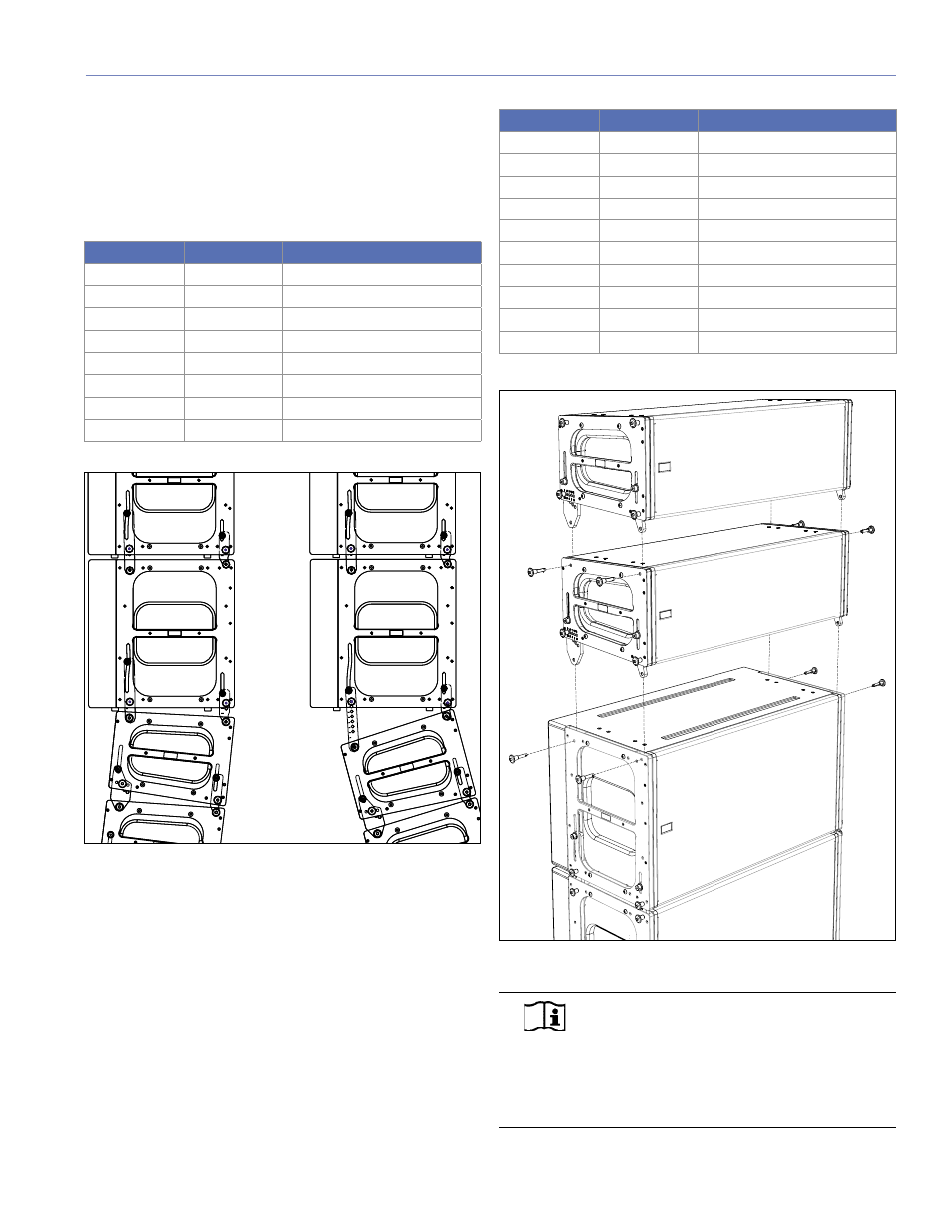
Ground-stacked
When MICAs are ground-stacked above the 600-HP, the
GuideALinks in MICA allow the same combinations as when
a MICA is linked with another MICA but it will create uptilt
instead of downtilt. The use of the +7 position on the front
GuideALink is not recommended.
Table 7.4. MICA Link Positions to 600-HP (ground-stacked)
Rear
Front
Angle for MICA
0
0
0°
0.5
0
0.5° uptilt
1
0
1° uptilt
1.5
0
1.5° uptilt
2
0
2° uptilt
2.5
0
2.5° uptilt
3
0
3° uptilt
4
0
4° uptilt
5
0
5° uptilt
6
0
6° uptilt
Figure 7.6. 600-HP and MICA in a ground-stacked configuration
NOTE:
The optional MDTL-MICA downtilt
link can be used between the top 600-HP
and the first MICA in the ground-stacked array to
add a fixed amount of downtilt to the MICA section.
For more information, please see the MG-MICA
Assembly Guide (part number 05.147.034.01).