Chapter 3: amplification and audio, Chapter 3: amplification and audio – Meyer Sound 600-HP User Manual
Page 15
9
CHAPTER 3
The 600-HP uses sophisticated amplification and protec-
tion circuitry to produce consistent and predictable results
in any system design. This chapter will help you under-
stand and harness the power of the 600-HP amplifier and
audio systems.
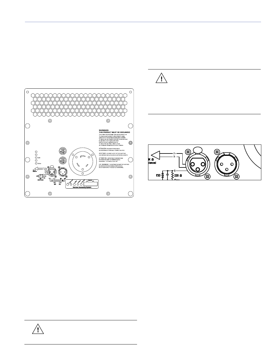
The rear panel of the 600-HP (Figure 3.1) provides AC
connection, audio input and loop out.
������
Figure 3.1. The rear panel of the 600-HP
AUDIO INPUT
The 600-HP presents a 10 kOhm balanced input imped-
ance to a three-pin XLR connector with the following
connections:
■
Pin 1 — 220 kOhm to chassis and earth ground (ESD
clamped)
■
Pin 2 — Signal ( + )
■
Pin 3 — Signal ( - )
■
Case — Earth (AC) ground and chassis
Pins 2 and 3 carry the input as a differential signal; pin
2 is hot relative to pin 3, resulting in a positive pressure
wave when a positive signal is applied to pin 2. Pin 1 is
connected to earth through a 220 kOhm, 1000 pF, 15 V
clamp network. This ingenious circuit provides virtual
ground lift for audio frequencies, while allowing unwanted
signals to bleed to ground.
CAUTION:
Shorting an input connector pin
to the case can form a ground loop and
cause hum.
Use standard audio cables with XLR connectors for bal-
anced signal sources. Make sure that pin 1 (shield) is
always connected on both ends of the cable. Telescoping
grounding schemes are not recommended.
CAUTION:
Ensure that all cabling carry-
ing signal to 600-HPs in a system is wired
correctly: Pin 1 to Pin 1, Pin 2 to Pin 2, and so
forth, to prevent the polarity from being reversed.
Any number of loudspeakers with reversed polarity
— even one in the subwoofer system — will result
in severe performance degradation.
Audio signals can be daisy-chained using the loop output
connector on the User Panel (Figure 3.2). A single source
can drive multiple 600-HPs with a paralleled input loop,
creating an unbuffered hard-wired loop connection.
Figure 3.2. 600-HP rear panel audio input connectors
When driving multiple 600-HPs in a system, make certain
that the source device can drive the total load impedance
presented by the paralleled input circuit of the system. The
audio source must be capable of producing 20 dBV (10
volts rms into 600 ohms) in order to produce the maximum
peak SPL over the operating bandwidth of the subwoofer.
To avoid distortion from the source, make sure the source
equipment provides an adequate drive circuit design for
the total paralleled load impedance presented by the
system. The input impedance for a single subwoofer is
10 kOhms. This is easy to calculate: if n represents the
number of 600-HPs in a system, paralleling the inputs of
n subwoofers will produce a balanced input load of 10
kOhms divided by n.
For example, cascading ten 600-HPs produces an input
impedance of 1000 ohms (10 kOhms divided by 10). The
source equipment should have an output impedance of
100 ohms or less. This is also true when connecting
600-HPs in parallel (loop out) with other self-powered
Meyer Sound loudspeakers, for example, MICA, CQ-1,
CQ-2, UPA-1P, and UPA-2P.
CHAPTER 3: AMPLIFICATION AND AUDIO