3 back panel and interface terminals – Maxtor QSNDVR9M User Manual
Page 14
-
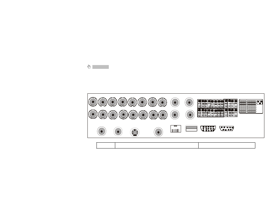
2.3 Back panel and interface terminals
Attention: The real connections on the back panel might be slightly
different from the sketch below.
2.3.1 Back panel of 16-channel DVR
CAM1 CAM2 CAM3 CAM4 CAM5 CAM6 CAM7
CAM8 AUDIO IN 1 AUDIO IN 2
ALARM IN
ALARM OUT
1 2 3 4 5 6 7 8 1 2 3 4
CAM9 CAM10 CAM11 CAM 12 CAM13 CAM1 4 CAM15 CAM16
SPOT OUT VIDEO OUT
S VIDEO
AUDIO OUT
AUDIO IN 3 AUDIO IN 4
9 10 11 12 13 14 15 16
CO M
+
GN D
RS-48 5
LAN
USB
VGA
RS-2 32
Back panel of 16-channel DVR
Num Icon
Description
Page 16
This manual is related to the following products: