Front panel connector: jfp1, Audio amplifier connector: jamp1 (for option c, e) – MSI IM-945GSE SERIES MS-9830 User Manual
Page 44
2-16
MS-9830 Mainboard
PIN
SIGNAL
DESCRIPTION
1
HD_LED +
Hard disk LED pull-up
2
FP PWR/SLP
MSG LED pull-up
3
HD_LED -
Hard disk active LED
4
FP PWR/SLP
MSG LED pull-up
5
RST_SW -
Reset Switch low reference pull-down to GND
6
PWR_SW -
Power Switch low reference pull-down to GND
7
RST_SW +
Reset Switch high reference pull-up
8
PWR_SW+
Power Switch high reference pull-up
9
RSVD_DNU
Reserved. Do not use.
Pin Definition
Front Panel Connector: JFP1
The mainboard provides one front panel connector for electrical connection to the
front panel switches and LEDs. The JFP1 is compliant with Intel
®
Front Panel I/O
Connectivity Design Guide.
1
2
9
10
JFP1
HDD
LED
Reset
Switch
Power
LED
Power
Switch
+
-
-
+
-
+
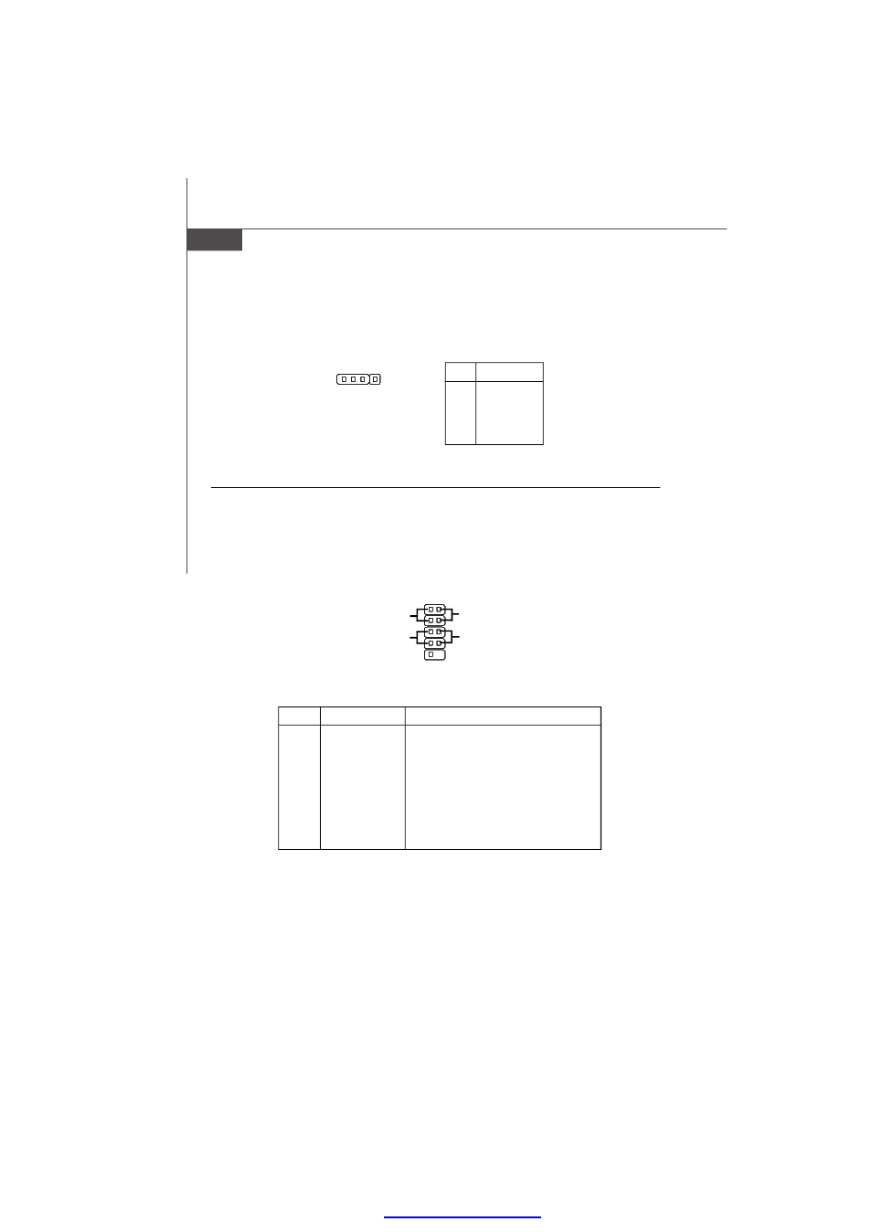
Audio Amplifier Connector: JAMP1 (for option C, E)
The JAMP1 is used to connect audio amplifiers to enhance audio performance.
PIN
SIGNAL
1
AMP_L-
2
AMP_L+
3
AMP_R-
4
AMP_R+
Pin Definition
1
JAMP1
PDF created with pdfFactory Pro trial versi
- AM-690E (68 pages)
- IM-GM45 (73 pages)
- IM-GM45 (1 page)
- MS-7304 (52 pages)
- MS-6534 (109 pages)
- NVIDIA MS-7504PV (50 pages)
- G52-M6570XA-G22 (116 pages)
- RG300EX LITE (53 pages)
- MS-7242 (102 pages)
- CX700 (66 pages)
- GM965 (76 pages)
- G31M3 (96 pages)
- Fuzzy Mainboard GM965 (76 pages)
- 845 PRO2 (101 pages)
- FUZZY CX700 (82 pages)
- MS-7181 (107 pages)
- G45 (95 pages)
- FUZZY 945GM1 (83 pages)
- US54G (41 pages)
- MS-6566 (85 pages)
- MS-6380 (85 pages)
- MS-6575 (68 pages)
- G52-S9617X1 (97 pages)
- G52-MA00628 (85 pages)
- MS-6523 (54 pages)
- ATX Motherboard G52-MA00362 (84 pages)
- N680GTX TWIN FROZR 4GD5/OC (1 page)
- N670 PE 2GD5/OC (1 page)
- N670GTX-PM2D2GD5/OC (1 page)
- N640GT-MD1GD3 (1 page)
- N630GT-MD4GD3 (1 page)
- N620GT-MD2GD3/LP (1 page)
- N610GT-MD2GD3/LP (1 page)
- N580GTX LIGHTNING XTREME EDITION (2 pages)
- N580GTX TWIN FROZR II/OC (2 pages)
- N560GTX-TI M2D1GD5/OC (2 pages)
- N560GTX-TI HAWK (2 pages)
- N560GTX-M2D1GD5 (2 pages)
- N460GTX-M2D1GD5/OC2 (2 pages)
- N460GTX HAWK TALON ATTACK (2 pages)
- N450GTS-MD1GD3 (2 pages)
- N440GT-MD1GD3/LP (2 pages)
- N430GT-MD1GD3/OC (2 pages)
- N220GT-MD1GD3/LP (2 pages)