Connector j10 interconnect signals (mvme712x), Table 3-11. connector j10 interconnect signals (mv, Connector j10 interconnect signals (mvme712 – Motorola MVME712B User Manual
Page 48: Table 3-11
Interconnect Signals
MVME712A/D3
3-15
3
Connector J10 Interconnect Signals (MVME712
x
)
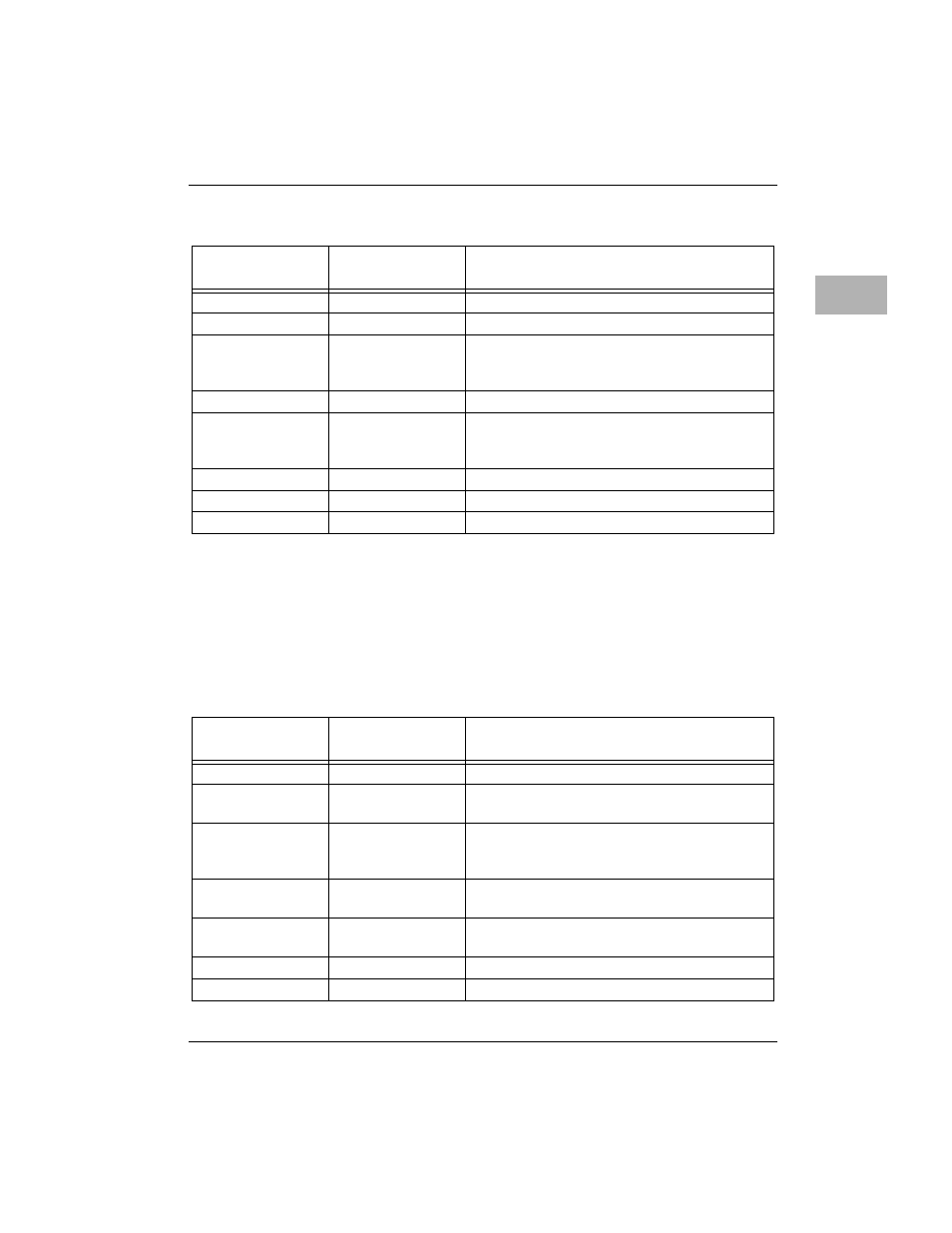
Connector J10 is the Ethernet interconnect on the MVME712x (MVME712A,
MVME712AM, MVME712-12, and MVME712-13). Each pin connection, signal
mnemonic, and signal characteristic for the connector is listed in
13
+12VMODEM
+12 Vdc Power - used by the modem.
14
+5VMODEM
+5 Vdc Power - used by the modem.
15
MDMRXD2
RECEIVE DATA - data that is demodulated
from the receive line is presented to the terminal
by the modem.
16
Not used.
17
MDMDCD2
DATA CARRIER DETECT - sent by the modem
to the terminal to indicate that a valid carrier is
being received.
18
GND
GROUND - modem circuit ground interface.
19
+5VMODEM
+5 Vdc Power - used by the modem.
20
GND
GROUND - modem circuit ground interface.
Table 3-11. Connector J10 Interconnect Signals (MVME712
x)
Pin
Number
Signal
Mnemonic
Signal Name and Description
1
Not used.
2
C-
COLLISION - (Output) - part of a differential
pair.
3
C+
COLLISION + (Input) - a signal to indicate that
multiple stations are contending for access to the
transmission medium.
4
T-
TRANSMIT - (Output) - part of a differential
pair.
5
T+
TRANSMIT + (Output) - this line is intended to
operate into terminated transmission lines.
6,7
Not used.
8
R-
RECEIVE - (Input) - part of a differential pair.
Table 3-10. Connector J7 Interconnect Signals (MVME712-13/AM) (Continued)
Pin
Number
Signal
Mnemonic
Signal Name and Description