Connector j15 interconnect signals (mvme712x), Table 3-14. connector j15 interconnect signals (mv, Connector j15 interconnect signals (mvme712 – Motorola MVME712B User Manual
Page 54: Table 3-14
Interconnect Signals
MVME712A/D3
3-21
3
Connector J15 Interconnect Signals (MVME712
x
)
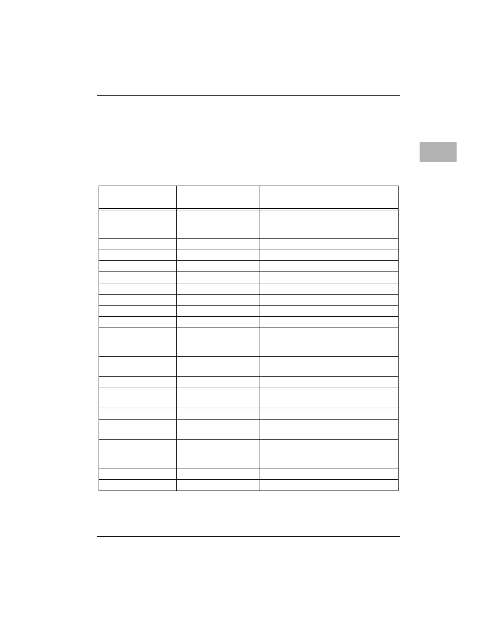
Connector J15 is the printer port on the MVME712x (MVME712-12,
MVME712-13, MVME712A, and MVME712AM). Each pin connection, signal
mnemonic, and signal characteristic for the connector is listed in
Table 3-14. Connector J15 Interconnect Signals (MVME712
x)
Pin
Number
Signal
Mnemonic
Signal Name and Description
1
PRSTB*
DATA STROBE - an active low output
pulse used to clock data from the system
to the printer.
2
PRD0
DATA (bit 0)
3
PRD1
DATA (bit 1)
4
PRD2
DATA (bit 2)
5
PRD3
DATA (bit 3)
6
PRD4
DATA (bit 4)
7
PRD5
DATA (bit 5)
8
PRD6
DATA (bit 6)
9
PRD7
DATA (bit 7)
10
PRACK*
DATA ACKNOWLEDGE - a low level
input pulse indicating that the next
character may be sent.
11
PRBSY
BUSY - an input signal indicating that the
printer cannot receive data.
12
PRPE
PAPER EMPTY - out of paper.
13
PRSEL
SELECTED - an input signal indicating
that the printer is selected.
14
Not used.
15
PRFAULT*
FAULT - an input signal that indicates a
printer fault condition.
16
INPRIME*
INPUT PRIME - an output signal that
clears the printer buffer and initializes the
logic.
17
Not used.
18-25
GND
GROUND