General information, Introduction, Features of the mvme712 family modules – Motorola MVME712B User Manual
Page 12
MVME712A/D3
1-1
1
GENERAL INFORMATION
Introduction
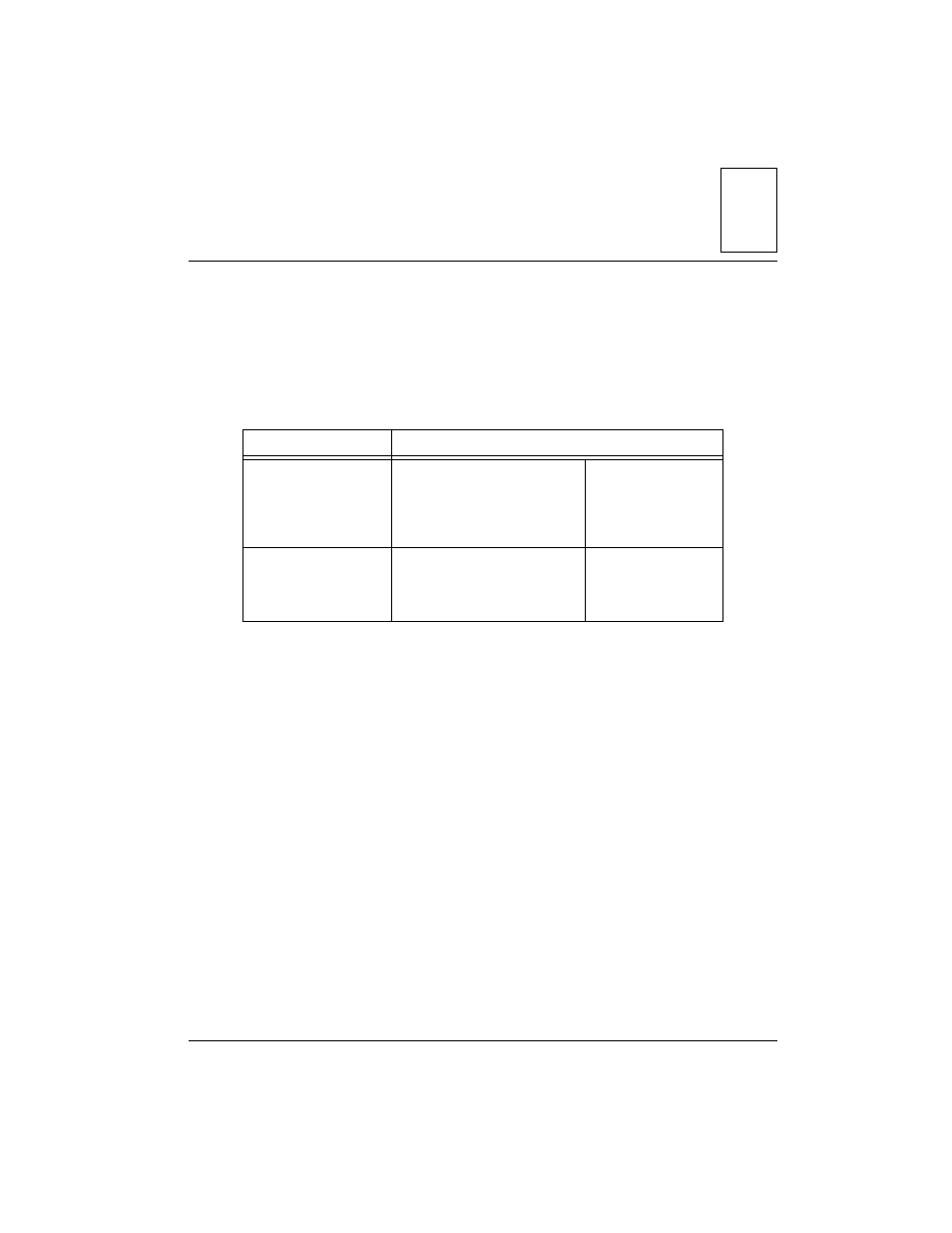
This manual provides general information, hardware preparation, installation
instructions, and support information for the MVME712A, AM, -12, -13, and B
Transition Modules, as well as the LCP2 Adapter Board. The next table
defines the references you will see throughout the manual.
The MVME712
x
modules are used as the interface between MVME1
xx
family
VMEmodules (such as the MVME167 and MVME197) and their internally
connected SCSI peripheral devices.
The MVME712B is designed to be used only
in conjunction with
an MVME712
x
board for external SCSI and/or Ethernet connections.
An LCP2 adapter module and a cable are supplied for interconnection
between the MVME712 family module and the MVME1
xx
family
VMEmodule.
Features of the MVME712 Family Modules
The features of the MVME712 family modules include:
❏
Four 9-pin multiprotocol EIA-232D serial ports (through the LCP2
adapter) (MVME712
x
)
❏
One independent printer port (through the LCP2 adapter) (MVME712
x
)
❏
Small Computer Systems Interface (SCSI) shielded connector bus interface
(through the LCP2 adapter) for connection to external devices
(MVME712B)
Collective Reference
Modules Referred To
MVME712 family
all
of the MVME712
modules, including the
MVME712B
MVME712-12
MVME712-13
MVME712A
MVME712AM
MVME712B
MVME712
x
all MVME712 modules
other
than the MVME712B
MVME712-12
MVME712-13
MVME712A
MVME712AM