Connector j6 interconnect signals (mvme712-13, mvm, Table 3-9. connector j6 interconnect signals (mvme, Connector j7 interconnect signals (mvme712-13, mvm – Motorola MVME712B User Manual
Page 47: Table 3-10. connector j7 interconnect signals (mvm, Table 3-9, Table 3-10
Support Information
3-14
MVME712-12/-13/A/AM/B Transition Modules and LCP2 Adapter Board UserÕs Manual
3
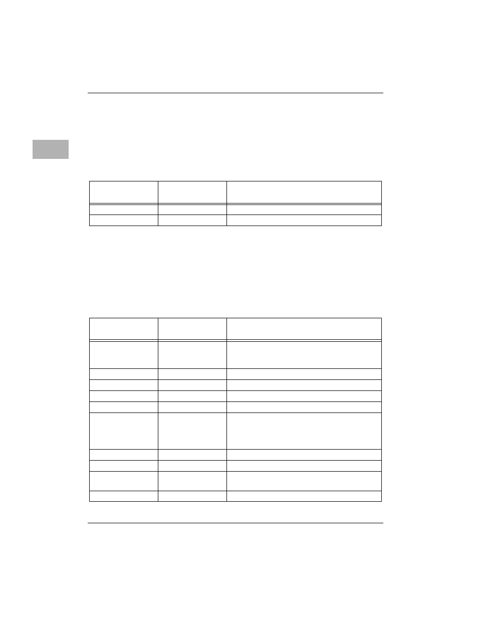
Connector J6 Interconnect Signals (MVME712-13, MVME712AM)
Connector J6 is the modem RING and TIP from the Telco front panel jack on
the MVME712-13 and MVME712AM. Each pin connection, signal mnemonic,
and signal characteristic for the connector is listed in
Connector J7 Interconnect Signals (MVME712-13, MVME712AM)
Connector J7 is the onboard modem interconnect (refer to Appendix A for
details on the modem). Each pin connection, signal mnemonic, and signal
characteristic for the connector is listed in
Table 3-9. Connector J6 Interconnect Signals (MVME712-13/AM)
Pin
Number
Signal
Mnemonic
Signal Name and Description
1
TIP
Tip side of telephone line.
2
RING
Ring side of telephone line.
Table 3-10. Connector J7 Interconnect Signals (MVME712-13/AM)
Pin
Number
Signal
Mnemonic
Signal Name and Description
1
MDMTXD2
TRANSMIT DATA - data to be transmitted is
furnished on this line to the modem from the
terminal.
2,3
Not used.
4
-12VMODEM
-12 Vdc Power - used by the modem.
5
+5VMODEM
+5 Vdc Power - used by the modem.
6
Not used.
7
MDMDTR2
DATA TERMINAL READY - an active low
signal from the terminal to the modem
indicating that the terminal is ready to send or
receive data.
8,9
Not used.
10
GND
GROUND - modem circuit ground interface.
11
MDMCTS2
CLEAR TO SEND - an active low signal that the
modem maintains in the on state.
12
Not used.