Connector scsi interface interconnect signals (mvm, Table 3-7. scsi interface interconnect signals (mv, Table 3-7 – Motorola MVME712B User Manual
Page 44
Interconnect Signals
MVME712A/D3
3-11
3
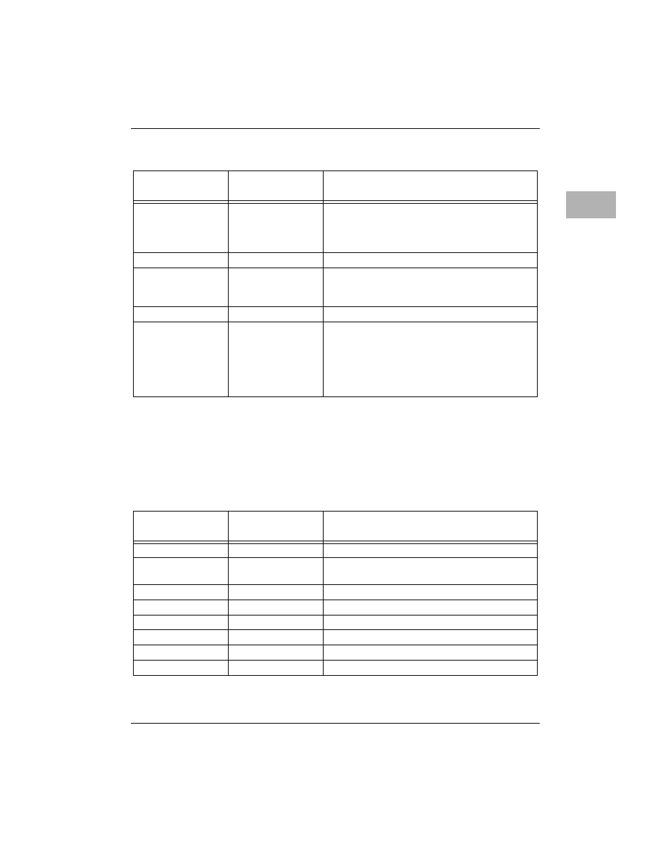
Connector SCSI INTERFACE Interconnect Signals (MVME712B)
Each pin connection, signal mnemonic, and signal characteristic for the
connector is listed in
.
46
D/C*
DATA/COMMAND - signal driven by the
target. It indicates whether command or data
information is on the data bus. True (low)
indicates command.
47
GND
GROUND
48
REQ*
REQUEST - signal driven by a target to indicate
a request for a REQ/ACK data transfer
handshake.
49
GND
GROUND
50
O/I*
OUTPUT/INPUT - signal driven by a target that
controls the direction of data movement on the
bus. True (low) indicates input to the initiator.
False (high) indicates output from the initiator.
This signal is also used to distinguish between
selection and reselection phases.
Table 3-7. SCSI INTERFACE Interconnect Signals (MVME712B)
Pin
Number
Signal
Mnemonic
Signal Name and Description
1-25
GND
GROUND
26
DB00*
DATA bus (bit 0) - least signiÞcant bit and the
lowest priority during the arbitration phase.
27
DB01*
DATA bus (bit 1)
28
DB02*
DATA bus (bit 2)
29
DB03*
DATA bus (bit 3)
30
DB04*
DATA bus (bit 4)
31
DB05*
DATA bus (bit 5)
32
DB06*
DATA bus (bit 6)
Table 3-6. Connector J3 Interconnect Signals (LCP2 Adapter) (Continued)
Pin
Number
Signal
Mnemonic
Signal Name and Description