Support information, Introduction, Interconnect signals – Motorola MVME712B User Manual
Page 34: Table 3-1. lcp2 and mvme712 connectors, Table 3-2. mvme712 jumpers, Introduction 3-1 interconnect signals 3-1
MVME712A/D33-1
3
SUPPORT INFORMATION
Introduction
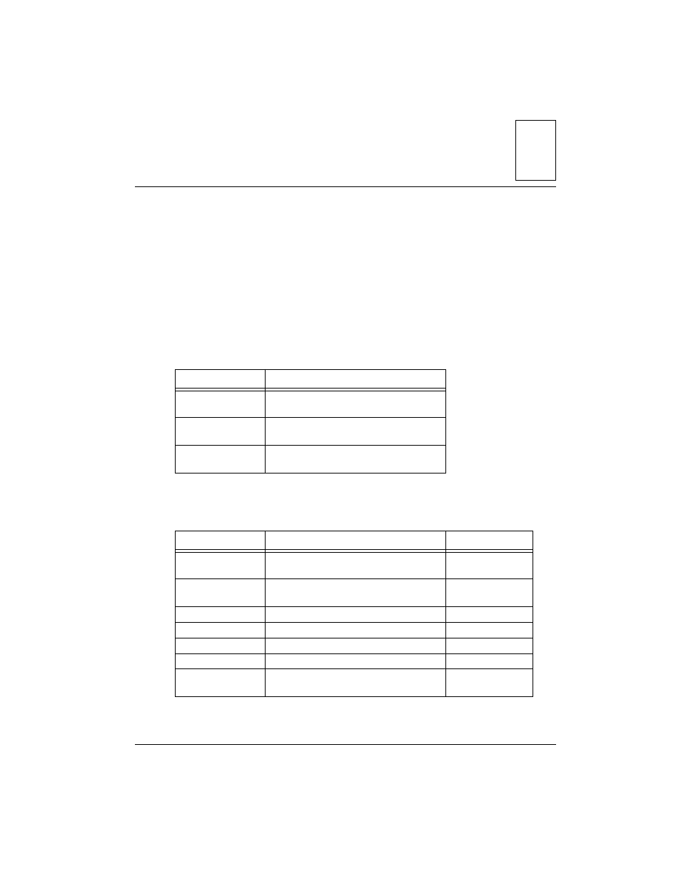
This chapter provides the interconnection signals, parts lists, parts location
illustrations, and schematic diagrams for the MVME712 family modules and
LCP2 adapter.
Interconnect Signals
describes the connections from the LCP adapter to the MVME712x
and VMEmodules:
lists the jumpers on the MVME712 modules.
Table 3-1. LCP2 and MVME712 Connectors
From
To
LCP2 adapter J2
J11 on the MVME712A
J11 on the MVME712AM
LCP2 adapter J2
P2 on the MVME712-12
P2 on the MVME712-13
LCP2 adapter P2
backplane at the MVME1xx
VMEmodule P2 connector
Table 3-2. MVME712 Jumpers
Jumper
Description
Modules
J1 and J3-J5
9-pin EIA-232D serial por
t
connectors
on the front panel
MVME712x
J15
25-pin
printer port connector on the
front panel
MVME712x
J2
6-pin modem power connector
MVME712x
J6
2-pin modem TIP/RING connector
MVME712x
J7
20-pin modem interconnect connector
MVME712x
J10
20-pin Ethernet connector
MVME712x
J12
Telco modular jack on the front panel
MVME712-13
MVME712AM