Miller Electric Miller DU-OP User Manual
Page 66
OM-494 Page 62
Description
Part
No.
Dia.
Mkgs.
Item
No.
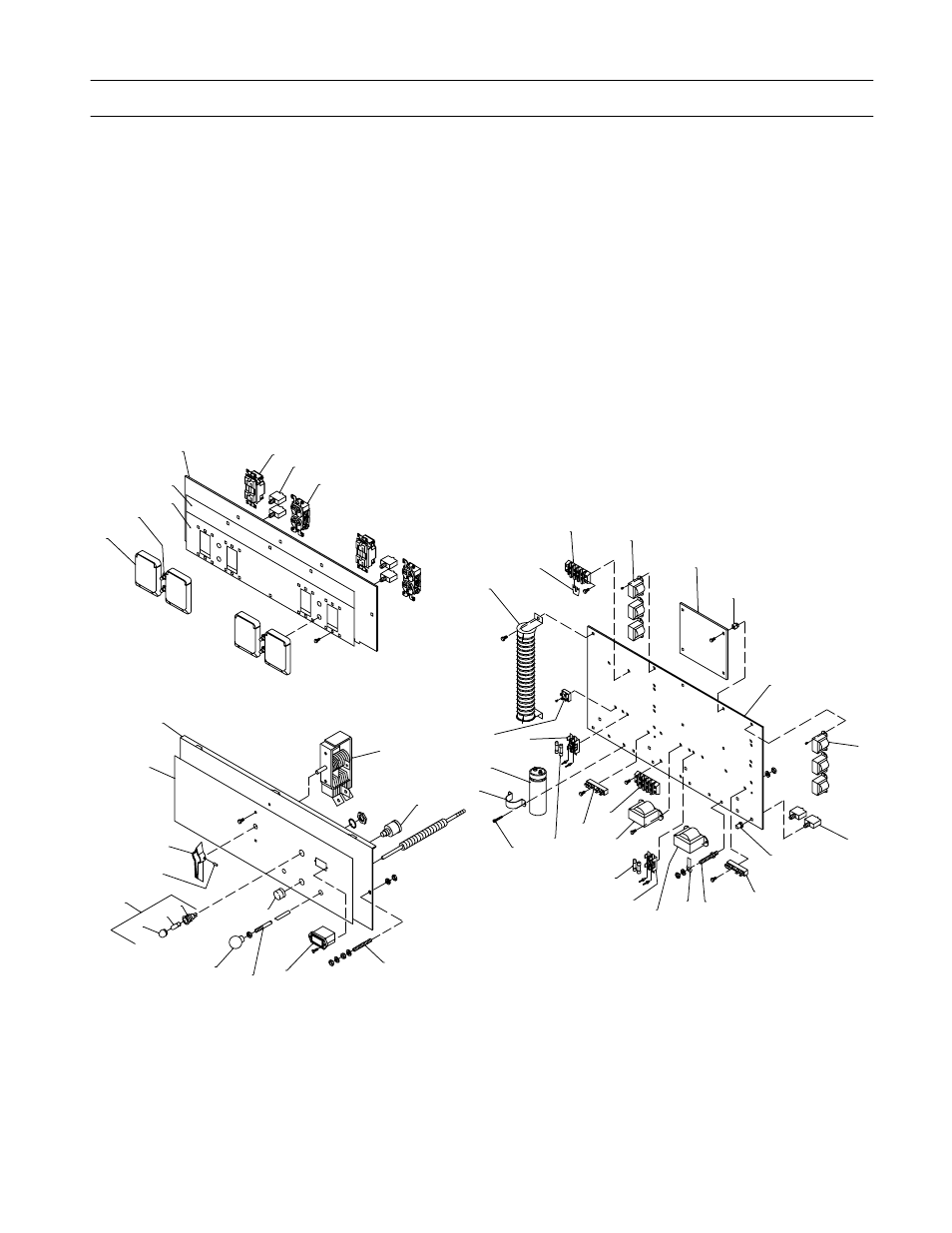
Figure 12-1. Main Assembly (Continued)
Quantity
201 915
KIT, label (includes safety and informational labels)
1
. . . . . . . . . . . . . . . . . .
. .
. . . . . . . . . . . . . . . . . . . .
201 916
KIT, label (includes safety and informational labels)
. . . . . . . . . . . . . . . . . .
. .
(Models w/opt. Polarity Switch)
1
. . . . . . . . . . . . . . . . . . . . . . . . . . . . .
. . . . . . . . . . . . . . . . . . . . . . . . . . . . . . . . . . . . .
+When ordering a component originally displaying a precautionary label, the label should also be ordered.
*Recommended Spare Parts.
♦
OPTIONAL
To maintain the factory original performance of your equipment, use only Manufacturer’s Suggested
Replacement Parts. Model and serial number required when ordering parts from your local distributor.
.
Hardware is common and
not available unless listed.
802 318-C
28
33
35
34
38
37
36
39
40
41
42
32
30
31
30
29
1
4
2
5
6
10
8
9
7
23
22
21
20
19
21
18
12
26
18
2
17
13
11
15
14
12
13
16
22
25
27
24
Figure 12-2. Front Panel