Dtv receiver with rgb video connections, Dtv receiver tv back pane, G (green) = y – MITSUBISHI ELECTRIC VS-50111 User Manual
Page 21: B (blue) = pb, R (red) = pr, Part ll: installation
21
21
C
on
ne
cti
ng a D
TV R
ec
eiv
er
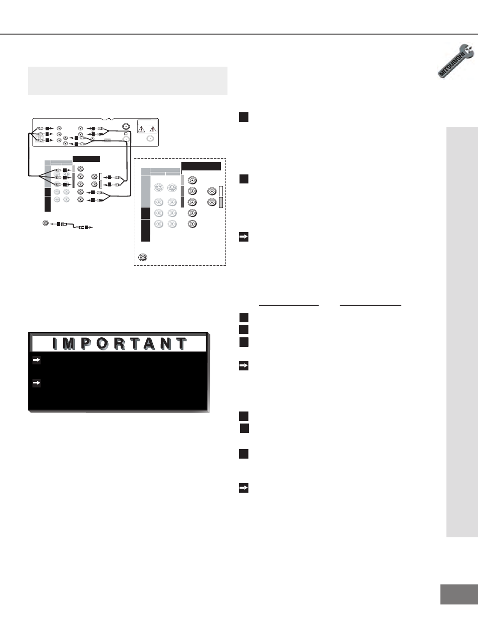
Connecting a DTV Receiver
DTV Receiver with RGB Video
Connections
(Figure 1)
1
Connect the outside antenna, cable, or
satellite to ANT or SATELLITE IN on the
DTV receiver (see your DTV receiver’s
owner’s guide for instructions and cable
compatibility).
2
Connect the incoming terrestrial antenna
or cable (not satellite) to ANT-A on the
TV back panel (a coaxial splitter, available
at most electronic supply stores, may be
required to complete this installation).
Connect the RGB cables from the DTV
receiver to the TV back panel as listed
below (if your DTV receiver uses BNC-type
cables, use the adaptors shown in
Figure 1, page 20):
DTV Receiver TV Back Pane
l
G (green)
=
Y
B (blue)
=
Pb
R (red)
=
Pr
If the DTV receiver has outputs for H
and V sync, connect as listed below (DO
NOT connect if DTV receiver uses “Sync
on Green”):
H (horizontal sync) =
H
V (vertical sync) =
V
8
Connect the L (left) and R (right) audio
cables from the DTV receiver and to DTV
AUDIO on the TV back panel.
To utilize the benefits of a digital
A/V receiver, connect your DTV receiver’s
digital audio out to a digital input on your
digital A/V receiver.
You may need to setup the DTV (See Input
Assignment, page 31) to RGB.
Figure 1. Connecting the DTV receiver with RGB video
connections.
DT V (Y PbPr/ GBRH V )
I N P U T
2
1
AN T - A
480 i / 480P /1080 i
AUDIO-
R IGH T
AUDIO-
LEFT /
(MONO)
Y
G
Pb
B
P r
R
V I D EO
S-VIDEO
V
H
DT V (Y PbPr/ GBRH V )
I N P U T
2
1
AN T - A
480 i / 480P /1080 i
AUDIO-
R IGH T
AUDIO-
LEFT /
(MONO)
Y
G
Pb
B
P r
R
V I D EO
S-VIDEO
V
H
TV back panel (Detailed View)
AUDIO
L
R
H
V
G
R
B
S-VIDEO
VCR
CONTROL
DIGITAL
AUDIO OUT
PHONE JACK
RF
REMOTE
SATELLITE IN
IN FROM ANT
OUT TO TV
CH 3
CH 4
CAUTION
RISK OF ELECTRICAL SHOCK
DO NOT OPEN
White
Red
4
3
5
6
7
6
7
8
8
8
8
3
4
5
2
Incoming Antenna,
or Cable.
2
See Appendix B, page 67, for RGB video
signal compatibility information.
For digital audio connections, see your
DTV receiver and A/V receiver Owner’s
Guides.
Note: The TV back panel and connections shown
here are for reference only and may vary by
model.
Part ll: Installation
3
4
5
6
7