Connecting the magnetic pickup, Connecting to cd ignition, Warning – Murphy Digital Tach/Hourmeter with Overspeed Trip Point SHD30 User Manual
Page 2: Connecting the overspeed output, Typical wiring, Overspeed output wiring, Figure 6
SHD3-97051N 2 of 4
TYPICAL WIRING
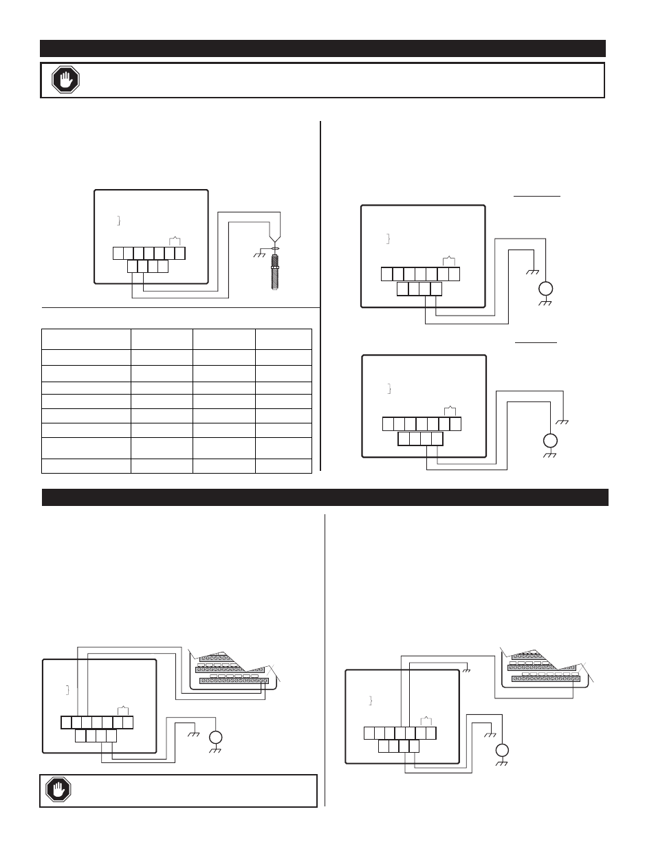
Connecting the Magnetic Pickup
Connect the magnetic pickup cable conductors to the 4-connector ter-
minal strip as shown in Figure 2. Use a two conductor shielded cable
between the SHD30 models and the magnetic pickup.
Connecting to CD Ignition
Before wiring the SHD30 models, determine the output voltage and
ground polarity of the ignition. Table 1 (below, left) lists the Peak
Output Voltage and Ground Polarity of some common ignitions.
Connect the SHD30 models to a positive or a negative ground CD
ignition as shown in Figures 3 or 4.
SHD30
5-120Vrms
Shield
ground
Magnetic Pickup
5 - 120Vrms
C. N.C.
+
+
–
–
N.O.
1
2
3
4
1
2
3
4
5
6 7
TB1
TB2
TB2
1 NO
2 C
3 NC
4 +Overspeed SCR
5 –Overspeed SCR
6
Reset Hourmeter
7
TB1
1 MPU +
2 MPU –
3 NEG 90-300vdc
4 POS 90-300vdc
5-120Vrms
Figure 2:
SHD30 models to magnetic pickup typical wiring
SHD30
CD Ignition
90-350VDC
+
—
IGN
C. N.C.
+
–
N.O.
1
2
3
4
1
2
3
4
5
6 7
TB1
TB1
1 MPU +
2 MPU –
3 NEG 90-300vdc
4 POS 90-300vdc
TB2
TB2
1 NO
2 C
3 NC
4 +Overspeed SCR
5 –Overspeed SCR
6
Reset Hourmeter
7
5-120Vrms
SHD30
CD Ignition
90-350VDC
+
—
IGN
C. N.C.
+
–
N.O.
1
2
3
4
1
2
3
4
5
6 7
TB1
TB2
TB2
1 NO
2 C
3 NC
4 +Overspeed SCR
5 –Overspeed SCR
6
Reset Hourmeter
7
TB1
1 MPU +
2 MPU –
3 NEG 90-300vdc
4 POS 90-300vdc
5-120Vrms
Figure 3:
SHD30 models typical wiring for NEGATIVE ground ignition
Figure 4:
SHD30 models typical wiring for POSITIVE ground ignition
Ignition
MFG & Series
Ground
Polarity
Peak Output
Voltage
Use Figure
Altronic III
Negative
225
3
Altronic II
Positive
350
4
Bendix S-1800, BLAR
Negative
250
3
Bendix Side-winder
Positive
300
4
Fairbanks Morse SCSA
Positive
180
4
Fairbanks Morse
3000 & 9000
Negative
225
3
American Bosch Magtronic
Negative
165
Altronic I & V
Negative
120
3
3
Table 1:
Output Voltage & Polarity of Common CD Ignitions
WARNING:
PERFORM THE WIRING INSTALLATION WITH THE POWER SOURCE OFF.
NEVER ROUTE THE SHD30 MODELS OVERSPEED OUTPUT LEADS WITH PRIMARY IGNITION WIRING.
16
17
32
Remove
Jumper
Back of MARK
III
CD Ignition
90-350VDC
+
—
IGN
C
NC
+
–
N O
1
2
3
4
1
2
3
4
5
6 7
TB1
TB2
TB2
1 NO
2 C
3 NC
4 +Overspeed SCR
5 –Overspeed SCR
6
Reset Hourmeter
7
TB1
1 MPU +
2 MPU –
3 NEG 90-300vdc
4 POS 90-300vdc
5-120Vrms
16
17
32
Leave Jumper
in place
Back of MARK
III
CD Ignition
90-350VDC
+
—
IGN
C
NC
+
–
NO
1
2
3
4
1
2
3
4
5
6 7
TB1
TB2
TB2
1 NO
2 C
3 NC
4 +Overspeed SCR
5 –Overspeed SCR
6
Reset Hourmeter
7
TB1
1 MPU +
2 MPU –
3 NEG 90-300vdc
4 POS 90-300vdc
5-120Vrms
OVERSPEED OUTPUT WIRING
Connecting the Overspeed Output
A 7-connector terminal strip, on the back of the SHD30 models, is pro-
vided for connection of the overspeed output. Terminals C., and N.C. are
used for connecting the output as a normally closed relay contact.
Terminals (+) and (–) are used for connecting the output as a normally
open SCR. Shown in Figure 5 is a typical wiring installation of the
SHD30 models normally closed relay output connected to a Murphy
MARK III digital annunciator. Figure 6 shows a typical wiring of the
SHD30 models normally open SCR output connected to a Murphy
MARK III digital fault annunciator. Figure 7 displays a typical wiring of
the SHD30 models normally open SCR output to a Murphy MARK IV
annunciator. Figure 8 displays a typical wiring of the SHD30 models nor-
mally closed relay output to a Murphy LCDT-NC annunciator. Figure 9
displays a typical wiring of the SHD30 models normally open SCR output
to a Murphy LCDT-NO annunciator.
Figure 5:
SHD30 models Normally Closed Relay output to MARK III
SHD30 To be
installed in accor-
dance with NEC
code for Class I,
Div. 2 Grps. C &
D hazardous
locations.
SHD30 models To be installed in accordance with NEC code for Class I,
Div. 2 Grps. C & D hazardous locations.
Figure 6:
SHD30 models Normally Open SCR output to MARK III
WARNING: Overspeed relay contact for use with FWMurphy non-
incendive or intrinsically safe products only.