Control options, Motor data – Modine Manufacturing 6-558.6 User Manual
Page 19
19
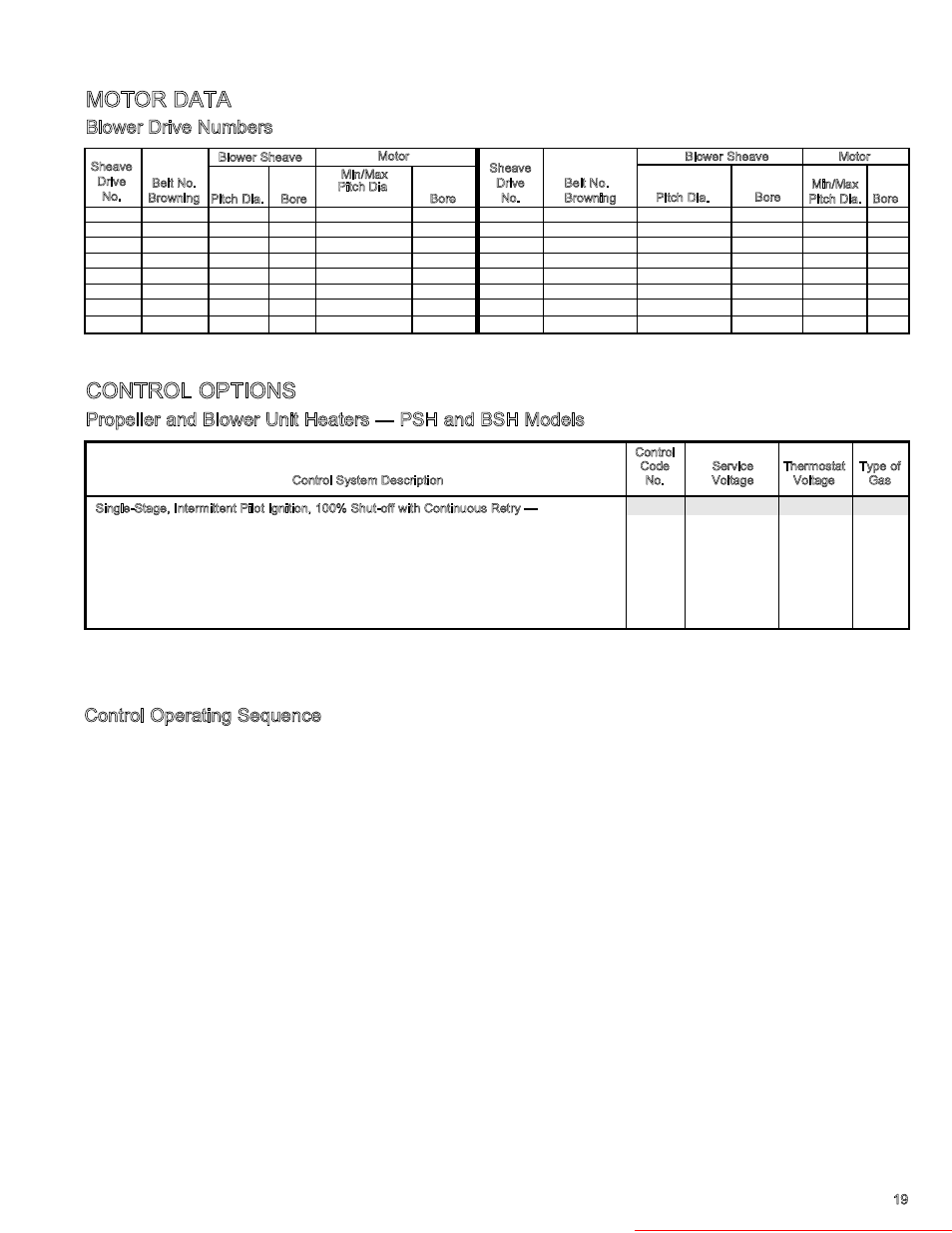
CONTROL OPTIONS
Control
Code
Service
Thermostat
Type of
Control System Description
No.
Voltage
Voltage
Gas
Single-Stage, Intermittent Pilot Ignition, 100% Shut-off with Continuous Retry —
30
115V
25V
natural
Utilizes a single-stage combination gas control and an ignition control (continuous retry).
31
200-208/230V
25V
natural
Pilot is automatically lit on call for heat.
➂
32
460V
25V
natural
➂ ➃
33
575V
25V
natural
85
115V
25V
propane
86
200-208/230V
25V
propane
➂
93
460v
25V
propane
➂ ➃
94
575v
25V
propane
Propeller and Blower Unit Heaters — PSH and BSH Models ➀ ➁ ➂ ➃
Control Operating Sequence
Upon a call for heat from the thermostat, power is supplied to
the time delay relay for the power exhauster motor. The power
exhauster motor will come on in 1 to 25 seconds. In 45 to 90
seconds (from the call for heat) the ignition control will be turned
on. This delay allows for a pre-purge of the unit and the vent.
Sparking will start at the igniter at the same time the first
operator of the combination gas control opens to allow ga to
flow to the pilot burner. The pilot flame should light and be
sensed (proven) in a few seconds. As soon as the pilot flame is
sensed the sparking will stop and the second operator of the
combination gas control will open to allow gas to flow to the
main burner. In 10 to 45 seconds from the time the ignition
control was energized (1 to 2 minutes from the call for heat from
the thermostat) the fan motor will start.
On units with control codes 08 and 09, when the ignition control
is turned on it will attempt to light the pilot flame. If the pilot
flame is not sensed for any reason, the sparking will continue
indefinitely until the pilot flame is sensed or until power is
interrupted to the ignition control. On units with control codes
30, 31, 85 and 86, the sequence is similar, except that when the
ignition control is turned on it will attempt to light the pilot
flame for 70 seconds. If the pilot flame is not sensed for any
reason, the ignition control will wait for a predetermined time
with the combination gas control closed and no sparking.
After the pre-determined time lapses, the cycle will begin
again. The time that lapses between cycles is at
preprogrammed intervals (approximately 6 minutes). This will
continue indefinitely until the pilot flame is sensed or until
power is interrupted to the ignition control.
When the thermostat has been satisfied, power is turned off
to the ignition control (and therefore the combination gas
control), so both the main gas and pilot gas are turned off.
The fan motor will continue to operate for 20 to 60 seconds to
allow the heat exchanger to cool down. Finally, the power
exhauster motor is turned off 1 to 2 minutes after the
thermostat is satisfied. This allows the products of
combustion to be cleared from the unit and the vent. The
system is now ready for another call for heat from the thermostat.
➀
Shaded prices - Standard units in stock; all others 2-3 weeks delivery.
➁
Stainless steel burner option - see page 5 for part number and list price.
➂
CGA approved 460V and 575V aviailable on blower units only.
➃
575V motor available on blower units only.
13
A43
8
0.750
1.9/2.9
0.500
25
A58
13
1.000
1.9/2.9
0.625
14
A44
8
0.750
1.9/2.9
0.625
32
A55
11
1.000
3.4/4.4
0.875
15
A44
9
0.750
1.9/2.9
0.500
57
A46
10
0.750
1.9/2.9
0.500
16
A48
8
1.000
1.9/2.9
0.625
165
A53
13
0.750
1.9/2.9
0.625
18
A49
9
1.000
1.9/2.9
0.625
166
A45
9
0.750
1.9/2.9
0.625
21
A52
13
0.750
1.9/2.9
0.500
167
A47
10
0.750
1.9/2.9
0.625
22
A53
11
1.000
1.9/2.9
0.625
177
A56
11
1.000
3.4/4.4
0.875
23
A56
11
1.000
3.4/4.4
0.625
178
A48
8
1.000
1.9/2.9
0.875
Sheave
Drive
No.
Belt No.
Browning
Blower Sheave
Motor
Pitch Dia.
Bore
Bore
Sheave
Drive
No.
Belt No.
Browning
Blower Sheave
Motor
Pitch Dia.
Bore
Min/Max
Pitch Dia. Bore
Min/Max
Pitch Dia.
MOTOR DATA
Blower Drive Numbers