Caution, Checking input rate, Heater parts from acf greenhouses – Modine Manufacturing 6-558.6 User Manual
Page 12
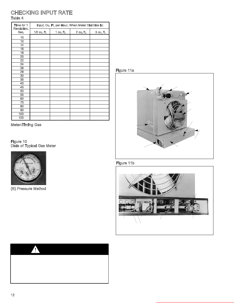
Table 4
Meter-Timing Gas
(Time required for one revolution is charted for various size
meter dials and various rates of gas input in cu. ft. per hour. To
convert to Btuh, multiply by the heating value of the gas used.)
Figure 10
Dials of Typical Gas Meter
(B) Pressure Method
The pressure method determines input by measuring the
pressure of the gas in the manifold in inches of water.
1.
Determine correct manifold pressure from Table 5.
2.
Remove access panel (see Figure 11a) and locate
combination gas control.
3.
Move gas control knob (or lever) to off.
4.
Remove the 1/8" pipe plug in outlet pressure tap in
combination gas control (see Figure 11b) and attach water
manometer or “U” tube which is at least 12" high.
5.
Follow lighting instructions and turn thermostat up to get
unit to fire.
6.
If pressure as indicated by “U” tube is less than 1/2" higher
or lower than indicated in TAble 5, adjust regulator as
described under “meter-Timing method,” Step 3.
If pressure as indicated by “U” tube is more than 1/2"
higher or lower than indicated in Table 5, check inlet
pressure at unit. The inlet pressure should be 6"-7" W.C.
pressure on natural gas and 11"-14" W.C. on propane gas.
After adjustment move gas control knob (or level) to off and
replace 1/8" pipe plug. With plug in place move knob (or leave)
to on.) Replace the access panel, making use a good tight seal
is achieved around the entire perimeter of the access panel.
VENTING
LABEL
POWER EXHAUSTER
PRESSURE
SWITCH
JUNCTION
BOX
FAN GUARD
FAN MOTOR
SIGHT GLASS
GAS SUPPLY
CONNECTION
(Not Shown)
ACCESS PANEL
COMBUSTION AIR
INLET COLLAR
LIGHTING
INSTRUCTION &
RATING PLATE
12
CHECKING INPUT RATE
Figure 11b
COMBINATION
GAS CONTROL
PRESSURE REGULATOR
ADJUSTMENT SCREW
(UNDER CAP SCREW)
MANIFOLD
PRESSURE TAP
PILOT
TUBING
IGNITION
CONTROL
IGNITION
CABLE
MAIN BURNER
MANIFOLD
Time for 1
Input, Cu. Ft. per Hour, When Meter Dial Size is:
Revolution,
Sec.
1/2 cu. ft.
1 cu. ft.
2 cu. ft.
5 cu. ft.
10
180
360
720
1800
12
150
300
600
1500
14
129
257
514
1286
16
112
225
450
1125
18
100
200
400
1000
20
90
180
360
900
22
82
164
327
818
24
75
150
300
750
26
69
138
277
692
28
64
129
257
643
30
60
120
240
600
35
51
103
206
514
40
45
90
180
450
45
40
80
160
400
50
36
72
144
360
55
33
65
131
327
60
30
60
120
300
70
26
51
103
257
80
22
45
90
225
90
20
40
80
200
100
18
36
72
180
120
15
30
60
150
Figure 11a
CAUTION
Check the gas inlet pressure at the unit upstream of the
combination gas control. The inlet pressure should be 6"-7"
W.C. on natural gas or 11"-14" W.C. on propane. If inlet pressure
is too high, install and additional pressure regulator upstream of
the combination gas control.
Important —Inlet pressure and manifold pressure must be
checked with unit in operation when making final adjustments.