Magnetek 144-45117-R3 User Manual
Page 6
Regenerative
Power
Module
-
September
2010
144-45117-R3
Page 6 of 20
Voltage Display
A 10-LED Switch Level bar graph provides a visual display of the approximate bus voltage level
when the brake transistor turns on.
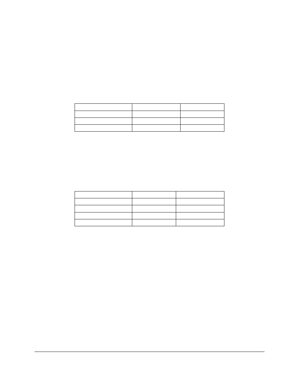
Simplified Switching Level Selection
An 8-position DIP switch provides transistor turn on switching level selection in 15 steps.
Link Setting
Adj Range
Volt/Step
330
256 – 400 VDC
16
495
384 - 600
24
660
512 - 800
32
Choose the appropriate setting for the voltage link set up and set the appropriate corresponding
DIP switch position on. All other DIP settings must be off.
• Mode Switches
A 4-position DIP switch provides the following configuration selections:
DIP Position
Off Setting
On Setting
1
Enable Ext Intlk Disable Ext Intlk
2
Auto Reset
Remote Reset
3
2-Term Res
3-Term Res
4
Not Used
Not Used
The External Interlock may be used for the connection of a normally closed temperature switch
mounted at the power resistor.
• Overheat Protection
The thermistor mounted on the heat sink is used to protect against failure caused by excessive
duty combined with excessive ambient temperatures. The unit is shut down when the heat sink
temperature exceeds 95° C.
• 24V Output for Fan
A +24V Fan output is available for supplemental cooling. The Fan output is capable of
delivering up to 5W for the addition of an external fan separately mounted from the RPM unit.
The output becomes active when the heat sink temperature exceeds 65° C.